Version 5.2 23 September 2007
SIP User's Manual 2. Physical Description
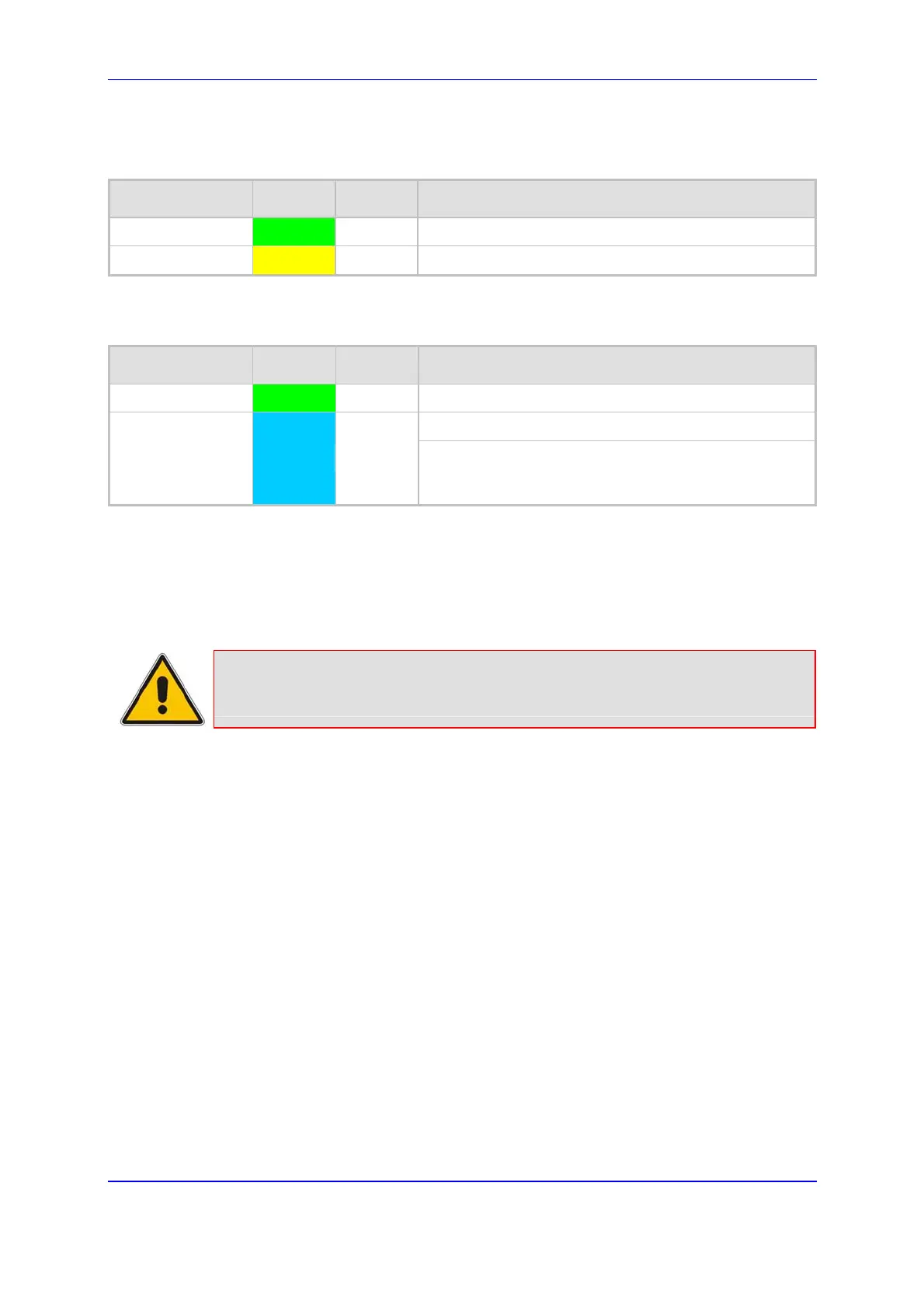
Table 2-6: Ethernet LEDs Description
Label Color Status Description
LINK Green
On Link all OK
ACT Yellow
On Transmit / receive activity
Table 2-7: cPCI LEDs Description
Label Color Status Description
PWR Green
On Power is supplied to the blade
The cPCI blade can be removed
SWAP READY Blue
On
The cPCI blade was inserted successfully (for detailed
information on inserting / removing the TP-1610 blade,
refer to 'Installing the TP-1610' on page 40)
2.2.2 TP-1610 Rear Transition Module
The Rear Transition Module (RTM) includes PSTN trunks, Ethernet interfaces, and an
optional RS-232 connector (available only on the 1-, 2- and 4-span configurations).
Note: RS-232 interface port is available on the RTM only for TP-1610 blades
supporting 1-, 2-, and 4-span configurations.
The Ethernet interface features dual 10/100 Base-TX, RJ-45 shielded connectors. This
dual interface provides an Ethernet redundancy scheme (active / standby), offering
protection against the event of Ethernet failure.
The PSTN interface is available in 1-, 2-, 4-, 8-, or 16-span rear panels. The connector type
on the RTM blade for these spans, depends on the number of spans supported by the
gateway:
 Loading...