E1 Series Servo Drive User Manual Basic Function Settings Before Operation
HIWIN MIKROSYSTEM CORP. 6-25
6.11 Electronic gear ratio
6.11.1 Introduction to electronic gear ratio
Controller controls the position of motor by inputting pulses. If the resolution of motor encoder is high and
the motor operates at high velocity, the output bandwidth of the controller or the input bandwidth of the
servo drive could be insufficient. At this time, users can use electronic gear ratio for adjustment. The
setting of electronic gear ratio affects the control unit displayed in Thunder. Control unit is the minimum
unit that the load moves for one pulse. Encoder resolution is required while setting electronic gear ratio.
For a 23-bit servo motor, 8388608 pulses need to be input for the motor to rotate for one revolution. The
examples of using and not using electronic gear ratio are provided as below.
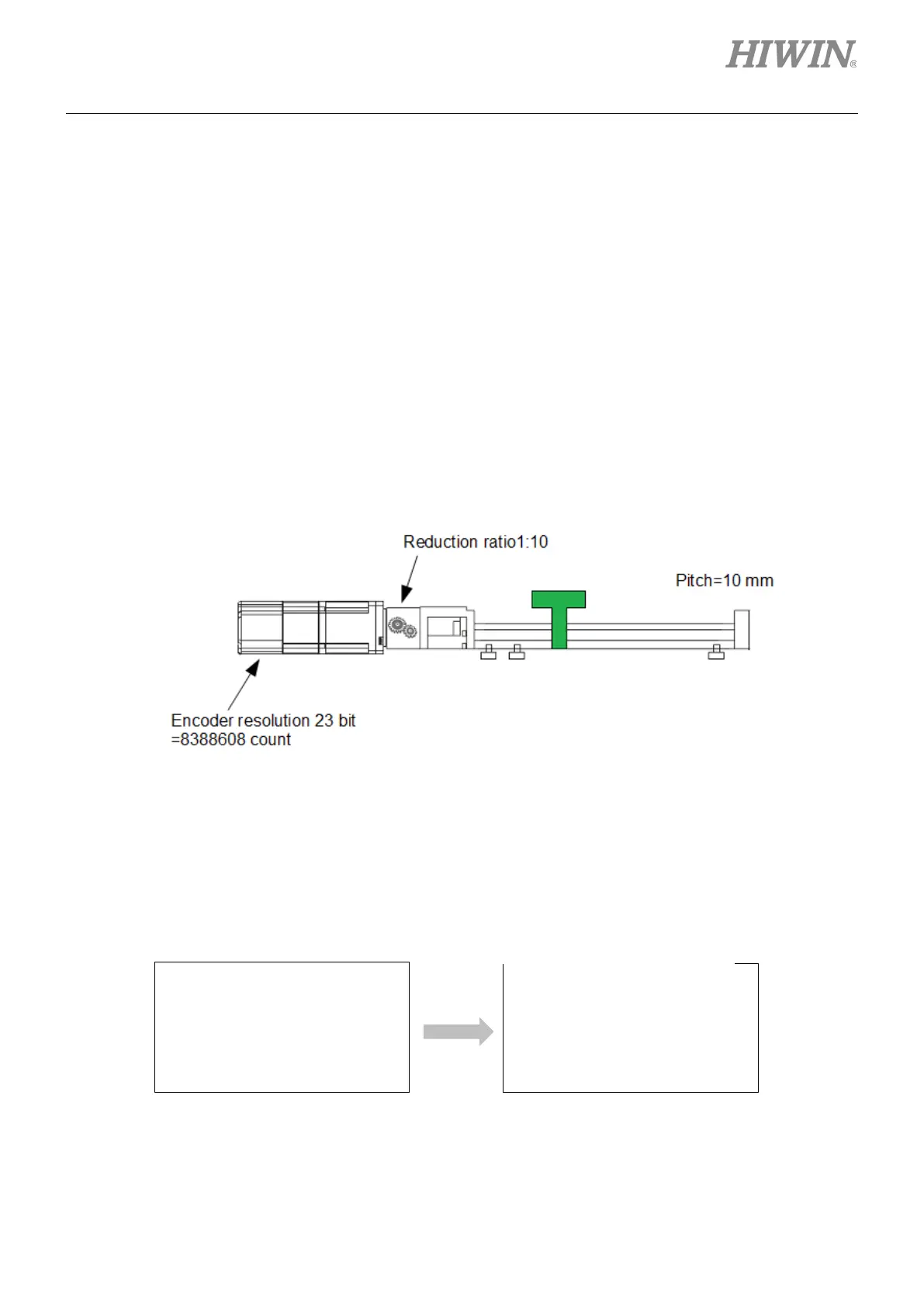
How many pulses should be input to let the load in figure 6.11.1.1 move for 15 mm in one second?
Figure6.11.1.1
Calculate the required revolutions to move the load for 15 mm.
Revolutions of screw=moving distance/screw pitch = 15/10 = 1.5
Revolutions of motor=revolutions of screw/reduction ratio = 1.5/0.1 = 15
Figure6.11.1.2
controller: 15*8388608 =
125829120 pulse/s =>
Bandwidth: At least 125.8 M
Control unit is 0.001 mm by
setting electronic gear ratio.
Pulse command from the
controller: 15/0.001 = 15000
pulse/s => Bandwidth: 0.015 M
Electronic gear ratio is not applied.
Electronic gear ratio is applied.
Calculation is complicated and
the required bandwidth is high.
Calculation is simple and
the required bandwidth is low.

 Loading...


