E1 Series Servo Drive User Manual Electrical Planning
5-24 HIWIN MIKROSYSTEM CORP.
5.4.2 Motor power connector (CN2)
The terminals used for connecting servo drive and servo motor are listed in table 5.4.2.1.
Table5.4.2.1
Name Description
U
U phase power
supply terminal
While using HIWIN motor power cable,
connect to the corresponding terminals by
referring to the symbols indicated on the
cable.
V
V phase power
supply terminal
W
W phase power
supply terminal
Note:
For information of motor power cable, please refer to table 16.1.1.1 in section 16.1.1.
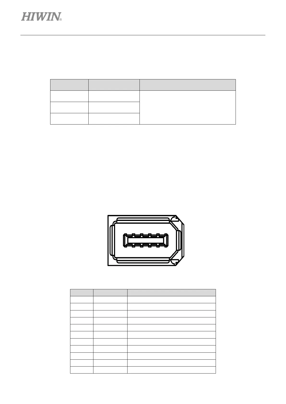
5.4.3 Encoder connector (CN7)
The encoder connector and its pin definition are shown as below. E1 series servo drive supports AC
servo motor with single-turn or multi-turn absolute encoder, dual loop control (AC servo motor and digital
optical scale) and linear motor with digital optical scale. For information of encoder setting, please refer to
section 6.12.
Figure5.4.3.1 Encoder connector (servo drive end)
Table5.4.3.1
Encoder serial signal: PS+
Encoder serial signal: PS-
Digital differential signal input: A+
Digital differential signal input: A-
Digital differential signal input: B+
Digital differential signal input: B-
Digital differential signal input: Index+
Digital differential signal input: Index-
SHIELD FG Shield

 Loading...


