E1 Series Servo Drive User Manual Application Function
8-32 HIWIN MIKROSYSTEM CORP.
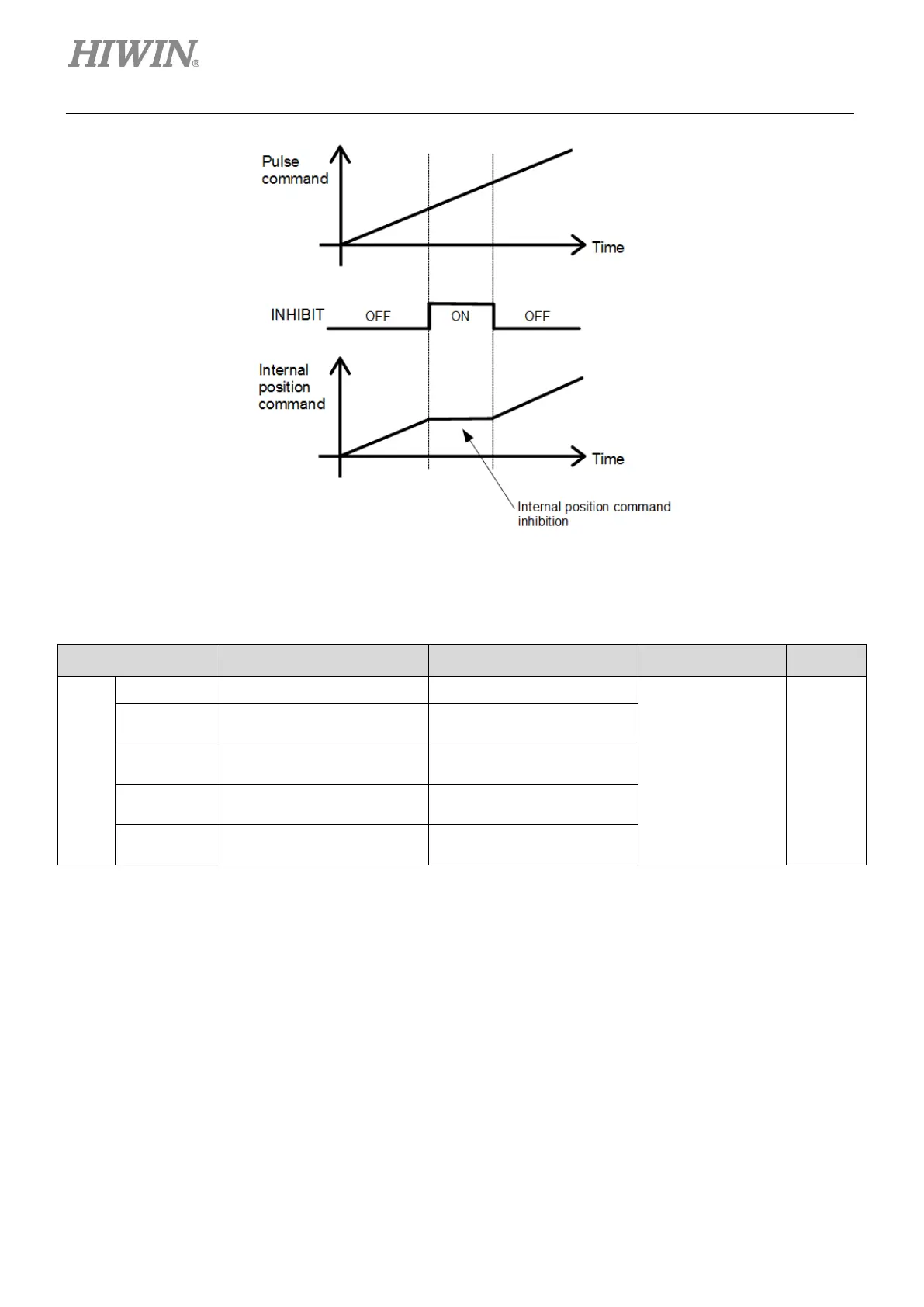
Figure8.4.6.1
Setting command pulse inhibition input function
Table8.4.6.2
Parameter Control Mode Input Signal Effective Category
Pt000
t.1 Position mode INHIBIT
After power on Setup
t.4
Internal velocity mode
↔Position mode
INHIBIT, C-SEL, SPD-A,
SPD-B, SPD-D
t.7
Position mode
INHIBIT, C-SEL
t.8
Position mode
INHIBIT, C-SEL
t.B
Internal position mode
INHIBIT, C-SEL
8.4.7 Position deviation clear input (CLR) signal
Position deviation clear input (CLR) signal is used to clear the deviation counter in the servo drive. When
CLR signal is ON, the deviation counter is 0. At this time, position loop control cannot be performed.
Note:
(1) The deviation counter shows the deviation between command pulses from controller and feedback pulses from
encoder.
(2) When position deviation clear input (CLR) signal is ON, do not input pulse command.

 Loading...


