E1 Series Servo Drive User Manual Application Function
HIWIN MIKROSYSTEM CORP. 8-7
8.1.2 Digital output signal allocation
This section describes how to allocate digital output signals to the desired pins. Each pin is allocated with
one default digital output signal when the servo drive is shipped out. Users can choose to use the default
setting or allocate digital output signals by themselves. Refer to the description below.
Use the default setting
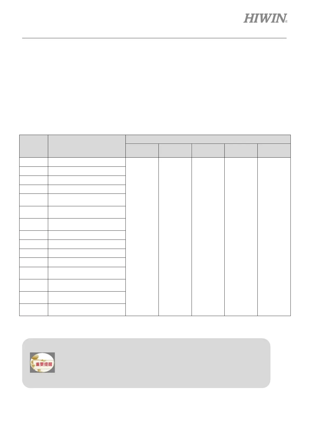
The default allocations of digital output signals are listed in table 8.1.2.1.
Table8.1.2.1
Pt000 =
t.X
Control Mode
CN6 Pin
35, 34
37, 36
39, 38
11, 10
40, 12
0 Velocity mode
COIN
&
V-CMP
TGON D-RDY ALM BK
1 Position mode
2 Torque mode
3 Internal velocity mode
4
Internal velocity mode
↔Position mode
5
Internal velocity mode
↔Velocity mode
6
Internal velocity mode
↔Torque mode
7 Position mode ↔Velocity mode
8 Position mode↔Torque mode
9 Torque mode↔Velocity mode
A Internal position mode
B
Internal position mode
↔Position mode
C
Internal position mode
↔Velocity mode
D
Internal position mode
↔Torque mode
E
Internal velocity mode
↔Internal position mode
Allocating digital output signals
In control mode which does not support a certain output signal, the output signal will
be OFF.
If the polarity of the pin for brake control output (BK) signal is inverted and the brake
operation is changed to negative logic, when the signal is OFF, the brake will stop
operating. Check the brake operation when power off and power on to avoid

 Loading...


