E1 Series Servo Drive User Manual Application Function
HIWIN MIKROSYSTEM CORP. 8-23
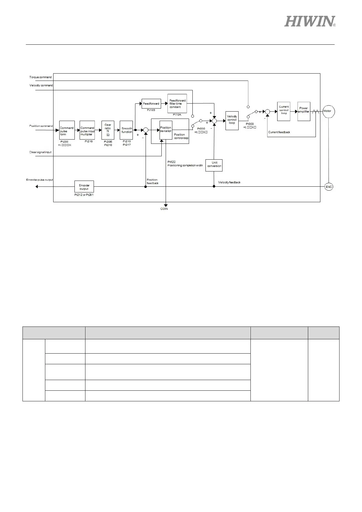
The control block diagram for position mode is as below.
Figure8.4.1
8.4.1 Setting position mode
Pulse command type and pulse command input filter are described in the following.
Pulse command type
Set pulse command type by Pt200 according to the pulse command from controller.
Table8.4.1.1
Parameter Description Effective Category
Pt200
Pulse signal (pulse + direction) (positive logic)
After power on Setup
t.1 Pulse signal (CW + CCW) (positive logic)
t.4
Differential pulse signal with 90 degrees phase difference
(A phase + B phase) x 4 (positive logic)
t.5 Pulse signal (pulse + direction) (negative logic)
t.6 Pulse signal (CW + CCW) (negative logic)

 Loading...


