E1 Series Servo Drive User Manual Software Settings And Trial Operation
HIWIN MIKROSYSTEM CORP. 7-7
7.5.1 SW method 1
While detecting electrical angle by SW method 1, refer to table 7.5.1.1 for applicable combinations of
motors and encoder signals.
Table7.5.1.1 Applicable combinations for SW method 1
Motor Encoder Signal Excellent Smart Cube (ESC)
Linear motor or direct drive
motor
Analog sin/cos signal Required (ESC-AN)
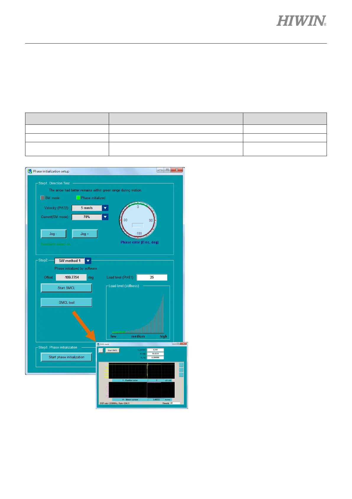
Figure7.5.1.1 Operating procedure of SW method 1
Select velocity and current for detecting electrical
angle. Click on Jog+ and Jog- buttons to move the
motor. While the motor is moving, check if the
electrical angle falls in the range colored in green.
Select SW method 1 and click on Start SMCL
button for three times. The difference of offset must
not exceed 5 deg.
Example:
Offset: 73.5 deg
Offset: 74.1 deg
Offset: 72.3 deg
Open SMCL tool and observe position deviation
during execution. If the position deviation is not
close to 0 within one second, it means the gain is
improper, please adjust load level.
Click on Start phase initialization button. Wait till
detection for electrical angle completes and check
Phase initialized indicator. If Phase initialized
indicator is green, it means electrical angle has
been successfully detected.
Note:
(1) If SW method 1 is executed under open loop control, the motor will be automatically disabled to avoid overheating when
it stops for a period of time.
(2) If the load level is too high, it may cause mechanical resonance.

 Loading...


