E1 Series Servo Drive User Manual Monitoring
HIWIN MIKROSYSTEM CORP. 11-3
11.2 Servo drive status
11.2.1 Monitoring servo drive status
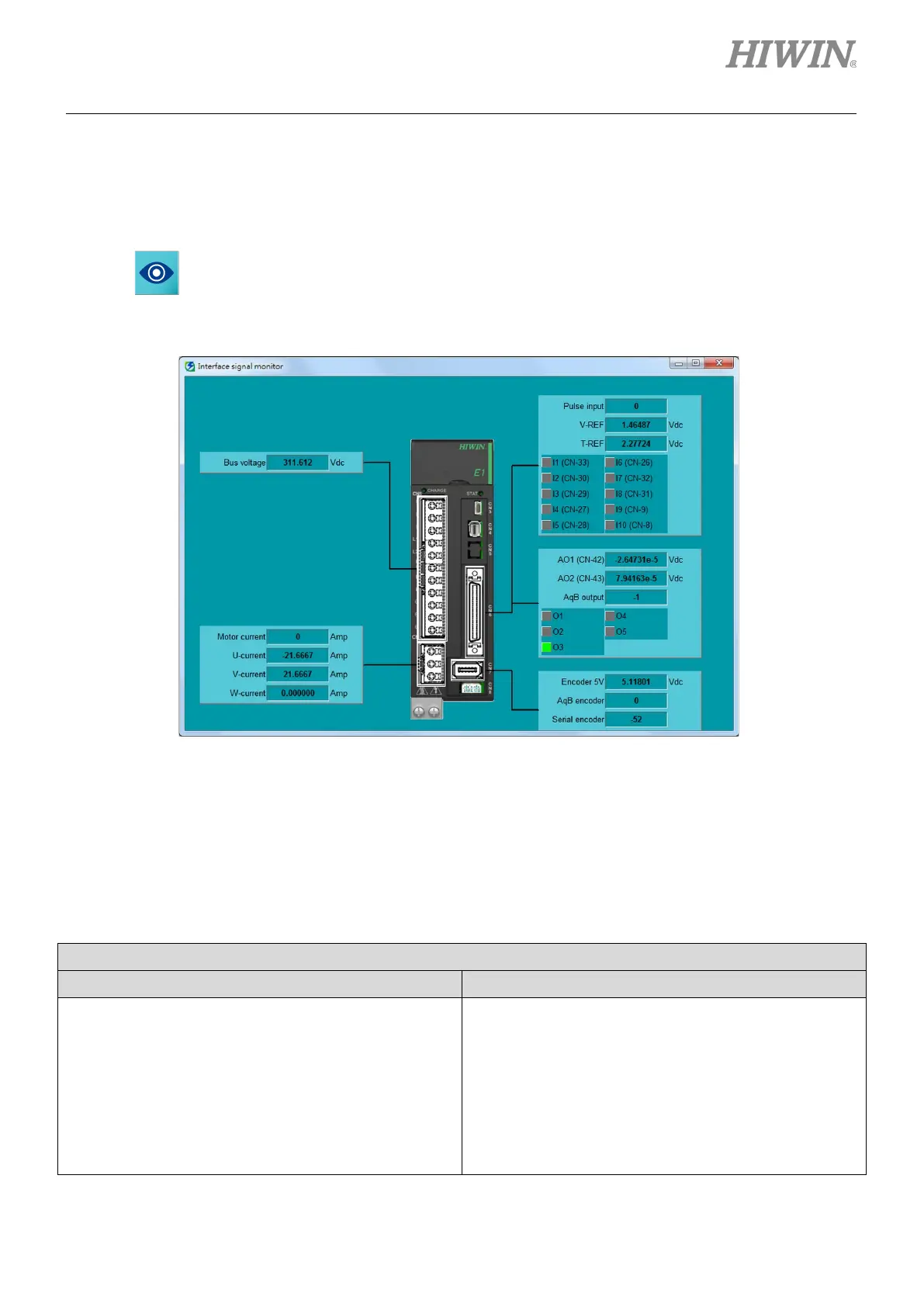
Click on in the main screen of Thunder to open Interface signal monitor window to monitor servo
drive status.
Figure11.2.1.1 The displayed information in Interface signal monitor window
11.2.2 Monitoring items of servo drive status
The monitoring items displayed in Interface signal monitor window are shown in table 11.2.2.1.
Table11.2.2.1
Monitoring Items
Internal Status I/O Signal Status
(1) The voltage of main power cable (Bus voltage)
(2) The position information of serial encoder (Serial
encoder)
(3) The position information of incremental encoder
(AqB encoder)
(4) The 5 Vdc voltage for encoder (Encoder 5V)
(5) The current of motor (Motor current)
(6) Three-phase current (U, V, W) (U, V, W-current)
(1) Pulse command input pulses (Pulse input)
(2) Encoder output pulses (AqB output)
(3) Velocity command voltage (V-REF)
(4) Torque command voltage (T-REF)
(5) Digital input signals (I1~I10)
(6) Digital output signals (O1~O5)
(7) Analog signal output voltage (AO1, AO2)

 Loading...


