EasyManuals Logo
Home>Hiwin>Servo Drives>E1 Series

Hiwin E1 Series User Manual

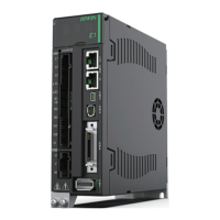
Hiwin E1 Series
394 pages
To Next Page IconTo Next Page
To Previous Page IconTo Previous Page
Page #62 background imageLoading...
Page #62 background image
E1 Series Servo Drive User Manual Electrical Planning
5-12 HIWIN MIKROSYSTEM CORP.
MD09UE01-1910
5.2 Wiring diagram for control mode
Position mode-Standard model, ED1S
Figure5.2.1
COM7
I133
I230
I329
I427
I528
I626
I732
I831
I99
4.7K
O1+ 35
O1- 34
O2+ 37
O2- 36
O3+ 39
O3- 38
O4+ 11
O4- 10
21A
22/A
48B
49/B
23Z
24/Z
19CZ
Encoder output
25SG
Signal output
S-ON
P-CON
P-OT
N-OT
ALM-
RST
26
P-CL
N-CL
HOM
MAP
24V
24V
R
General input
Defined by user
General output
Defined by user
A-phase
output
Z output (open collector)
0V
B-phase
output
Z-phase
output
W
V
U
CN2
CN7
COIN &
V-CMP
TGON
D-RDY
Photo-
Coupler
wiring
Relay
wiring
( :Twisted pair)
Ic=0.6A(Max.)
Vce=40V(Max.)
R
D/A
42AO1
43AO2
41AOGND
D/A
Monitor output
Voltage Meter
47PT+
46PT-
Position Trigger
HIWIN
E1 Series Drive
CN6
Controller: Position Mode
I108
FSTP
0V
O5+ 40
O5- 12
0V
R
ALM
BK
3 CW+
4 CW-
5
CCW+
6
CCW-
13 SG
PLS
DIR
CW / A
221
2.05K
221
1
PULH_CW
2
PULH_CCW
2.05K
2.05K
2.05K

Table of Contents

Other manuals for Hiwin E1 Series

Questions and Answers:

Question and Answer IconNeed help?

Do you have a question about the Hiwin E1 Series and is the answer not in the manual?

Hiwin E1 Series Specifications

General IconGeneral
BrandHiwin
ModelE1 Series
CategoryServo Drives
LanguageEnglish

Related product manuals