E1 Series Servo Drive User Manual Panel Operation
14-10 HIWIN MIKROSYSTEM CORP.
14.3.2 Monitoring input signals
Ut005 is used to monitor input signals. The state of input signal is displayed by the segment of LED.
Display
Figure14.3.2.1
LED numbers and their corresponding input signals
Table14.3.2.1
LED Number Input Hardware Pin Signal (Default)
1 CN6-33 S-ON
2 CN6-30 P-CON
3 CN6-29 P-OT
4 CN6-27 N-OT
5 CN6-28 ALM-RST
6 CN6-26 P-CL
7 CN6-32 N-CL
8 CN6-31 HOM
9 CN6-9 MAP
10 CN6-8 FSTP
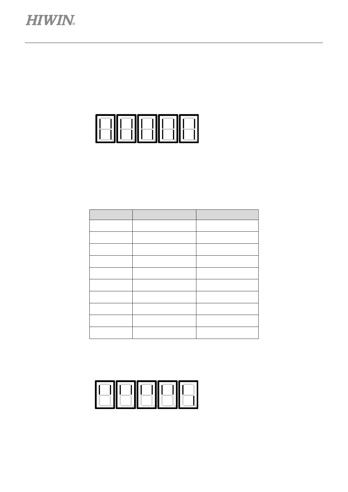
Display example
(1) Servo on input (S-ON) signal is ON.
Figure14.3.2.2
10 9 8 7 6 5 4 3 2 1 ←LED number
up: input signal is OFF.
The lower segment lights
of LED number 1 lights

 Loading...


