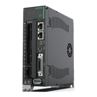
E1 Series Servo Drive User Manual Software Settings And Trial Operation
7-6 HIWIN MIKROSYSTEM CORP.
Table7.4.2.1 Combinations of customized servo motors/linear motors/direct drive motors and encoder signals
Motor Encoder Signal Excellent Smart Cube (ESC)
Linear motor or direct drive
motor
Analog sin/cos signal Required (ESC-AN)
Linear motor or direct drive
motor
Serial EnDat or BiSS-C signal (Not supported
yet)
Required (ESC-SA)
Linear motor or direct drive
motor
Analog sin/cos signal+digital Hall sensor signal Required (ESC-AN)
Table7.4.2.2 Inspection procedure for customized AC/LM/DM
Item Description Reference
Hardware
Step 1: Check if the servo drive is correctly installed inside the control box.
Step 2: Check the wiring of the servo drive.
CN1 power-Check the voltage of the input power. Check if the
connectors are firmly connected.
CN2 motor power-Check if the UVW power terminals on the servo drive
and motor power cable are correctly wired. Check if the terminals are
secure.
CN7 encoder-Check if the motor and the servo drive are firmly
connected. If Hall sensor is installed, check if the wiring and connectors
are secure.
Step 3: Confirm the encoder information. Ensure the software setting is correct.
Step 4: Loosen the coupling. Do not connect the motor and mechanism.
Software
Step 5: Download the latest version of Thunder. And connect to the servo drive.
Step 6: Do software setting by following the procedures provided in Thunder.
Step 7: Check the moving direction. Complete detection for electrical angle.
Step 8: Execute trial operation, such as JOG or point-to-point (P2P) motion.
Step 9: Operate with controller.
7.5 Detection for electrical angle
While using customized servo motor (AC), linear motor (LM) or direct drive motor (DM), detection for
electrical angle must be completed before closed loop control. E1 series servo drive provides two
detection methods: SW method 1 and Digital Hall.

 Loading...