E1 Series Servo Drive User Manual E1 Series Servo Drive
HIWIN MIKROSYSTEM CORP. 2-5
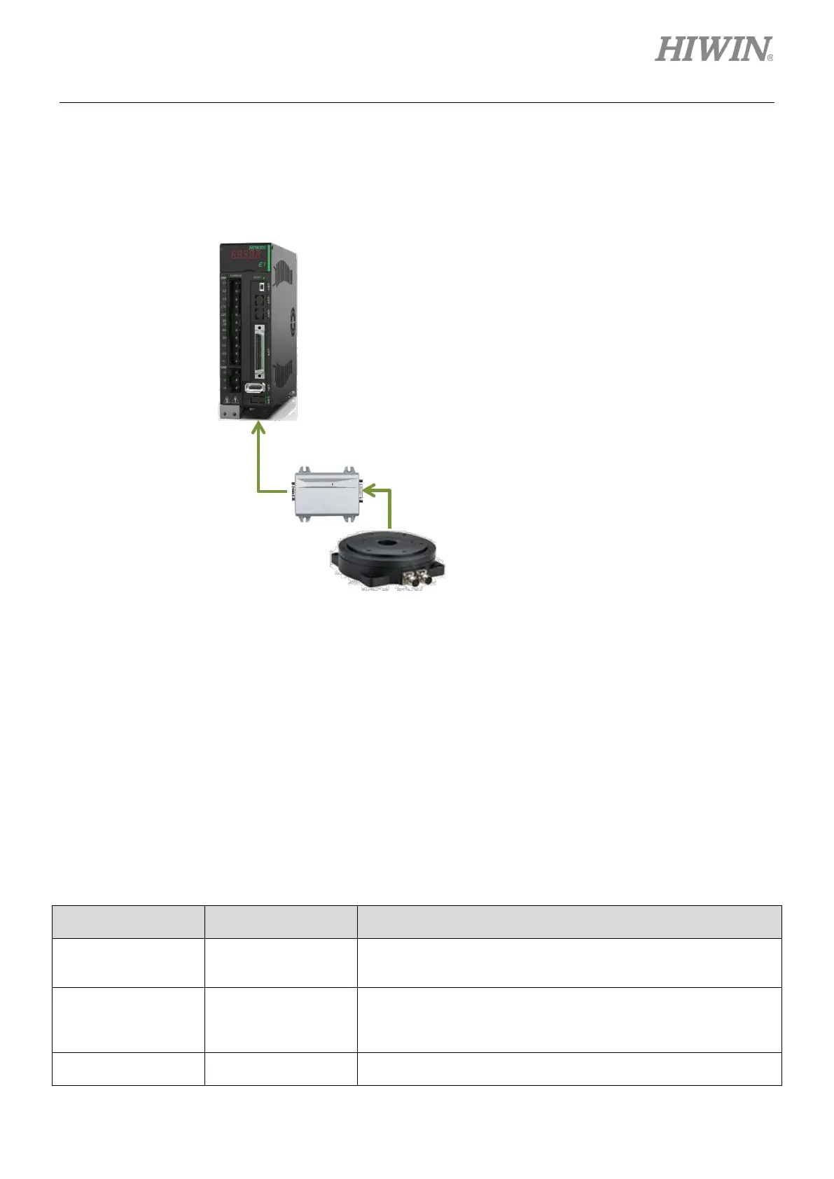
2.2.3 Direct drive motor (DM)
The supported encoder types when the servo drive is used with direct drive motor (DM) are shown in
figure 2.2.3.1.
Figure2.2.3.1
2.2.4 Motor current and servo drive current
The continuous current and peak current of a motor must not exceed the output current of the connected
servo drive. If not, the motor is unable to generate its rated force. Refer to table 2.2.4.1 to find proper
servo drive power.
Table2.2.4.1
Comparison of
Continuous Current
Comparison of
Peak Current
Output Force (Torque)
Servo drive > Motor Servo drive > Motor
The motor is able to generate the rated force (torque) and
instantaneous force (torque) of its specification. This combination
Servo drive > Motor Servo drive < Motor
The motor is able to generate the rated force (torque), but is
unable to generate the instantaneous force (torque) of its
specification. This combination could be used depending on users’
Servo drive < Motor Servo drive < Motor
The combination is not suggested. Use servo drive with larger
output power.
Excellent Smart Cube (ESC) is required when one
of the following signals is used as feedback signal
of direct drive motor.
Analog (sin/cos) encoder signal
EnDat encoder (Not supported yet)
BiSS-C encoder (Not supported yet)
Digital Hall signal
Thermal sensor
(1) Excellent Smart Cube (ESC) is usually required when standard HIWIN direct drive motor is used. For
related information, please refer to chapter 3.
(2) For information of cables, please refer to section 16.1.4.

 Loading...


