E1 Series Servo Drive User Manual Application Function
HIWIN MIKROSYSTEM CORP. 8-45
8.8.1 Setting internal velocity mode
The digital input signals and pins used for internal velocity mode are listed as below.
Default setting
Table8.8.1.1
Signal
CN6 Pin Description
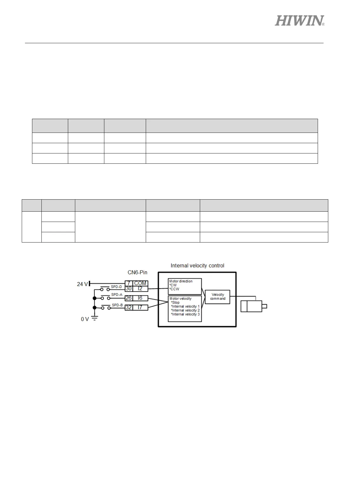
SPD-D I2 30 Change rotation direction.
SPD-A I6 26 Internal set velocity 1 input signal
SPD-B I7 32 Internal set velocity 2 input signal
Allocating input signals
Table8.8.1.2
Type Signal Hardware Pin Parameter Description
Input
SPD-D
User-defined
Pt50C = t.X Change rotation direction.
SPD-A Pt50C = t.X Internal set velocity 1 input signal
SPD-B Pt50C = t.X Internal set velocity 2 input signal
Figure8.8.1.1

 Loading...


