Home
Hiwin
Servo Drives
E1 Series
Hiwin E1 Series User Manual
4
of 1
of 1 rating
394 pages
Give review
Manual
Specs
To Next Page
To Next Page
To Previous Page
To Previous Page
Loading...
E1
Seri
es Servo
Drive Us
er Man
ual
Specification
HIW
IN MIKRO
SYST
EM C
ORP
.
4-5
MD0
9UE
01
-1
910
4.1.2
E1
ser
ies
ser
vo dr
ive
(
Fi
eldbus
)
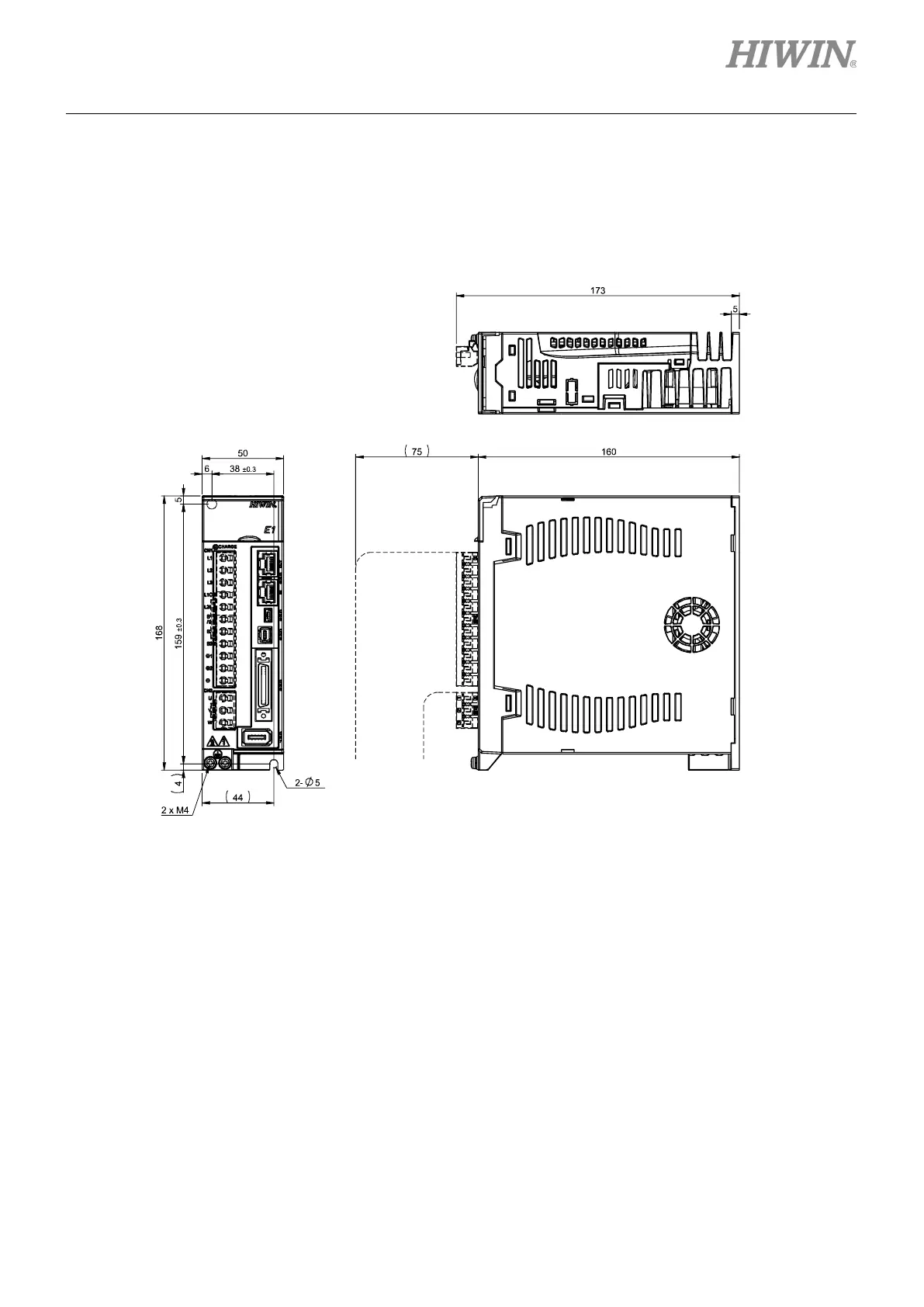
The model number of Fi
eldbus servo drive is ED1F.
400 W
servo drive (
Fieldbus
)
Figure4.1.
2.1 The d
imension
s of 400 W
servo
drive (
Fieldbus
)
40
42
Table of Contents
Table of Contents
21
Parameters ···························································································································
2
Servo Motor (AC) ··········································································································
3
E1 Series Servo Motor
19
E1 Series Servo Drive
20
Table of Contents
21
E1 Series Servo Drive
22
Model Explanation of Servo Drive
22
Nameplate
22
Model Explanation
22
Linear Motor (LM)
24
Excellent Smart Cube (ESC
24
Direct Drive Motor (DM)
25
Motor Current and Servo Drive Current
25
Specification
25
Selecting Regenerative Resistor
26
3. Excellent Smart Cube (Esc)
29
Excellent Smart Cube (ESC)
30
Model Explanation of Excellent Smart Cube (ESC)
30
Nameplate
30
Model Explanation
30
Dimensions of Excellent Smart Cube (ESC)
31
Terminals of Excellent Smart Cube (ESC)
32
Terminal Symbols and Terminal Names
32
Pin Definition
32
Status Indicator
34
ESC Specifications
35
ESC Hardware
35
ESC Cables
36
4. Specification
37
Dimensions of E1 Series Servo Drive
38
E1 Series Servo Drive (Standard)
38
E1 Series Servo Drive (Fieldbus)
41
Installation
44
Basic Specification
45
Selecting No-Fuse Breaker (NFB)
48
5. Electrical Planning
51
Electrical Planning
51
Wiring Precautions
52
General Precautions
52
Countermeasures against Interference
54
Grounding
60
Wiring Diagram for Control Mode
62
Wiring for Power Supply (CN1)
65
Terminal Symbols and Terminal Names
65
Wiring for Main Circuit Connector
66
Power-On Sequence
66
Wiring Diagram for Power Supply
68
Wiring for Regenerative Resistor
71
Wiring for DC Reactor
73
Wiring for Servo Motor
73
Terminal Symbols and Terminal Names
73
Motor Power Connector (CN2)
74
Encoder Connector (CN7)
74
Wiring for Brake
75
Control Signals (CN6)
76
Control Signal Connector
76
Wiring Example of Control Mode
79
Wirings for Digital Inputs and Digital Outputs
81
STO Connector (CN4)
84
Pin Definition of STO Connector
84
Wiring for STO Safety Function
85
Other Connectors
86
Connector for PC Communication (CN3)
86
Connector for Fieldbus Communication (CN9)
86
6. Basic Function Settings before Operation
89
Basic Function Settings before Operation
90
Parameters
90
Parameter Definition
90
Parameter List
91
Parameter Setting
93
Parameter Initialization
93
Control Modes
95
Automatic Motor Identification
96
Setting Main Circuit Power Supply
96
Setting Single-Phase/Three-Phase AC Power Input
96
Function and Setting of Servo on Input (S-ON) Signal
97
Function of Servo on Input (S-ON) Signal
97
Setting S-ON Signal to be Always on
97
Setting the Moving Direction of Motor
98
Overtravel Function
99
Overtravel Signals
100
Enabling/Disabling Overtravel Function
100
Motor Stopping Method for Overtravel
100
Overtravel Warning
102
Brake
103
Brake Operating Sequence
104
Brake Control Output (BK) Signal
104
Output Timing of BK Signal When Motor Stops
105
Output Timing of BK Signal When Motor Is Operating
106
Motor Stopping Methods for Servo off and Alarm
108
Motor Stopping Method When Servo off
108
Motor Stopping Methods for Alarm
109
Detection for Motor Overload
110
Detection Timing for Overload Warning (AL.910)
111
Detection Timing for Overload Alarm (AL.720)
111
Electronic Gear Ratio
113
Introduction to Electronic Gear Ratio
113
Setting Electronic Gear Ratio
114
Setting Encoder
116
Precautions for Initialization
116
Tool
117
Parameter Settings for Encoder
117
Encoder Delay Time
118
Setting Regenerative Resistor
118
Over Temperature Protection
119
7. Software Settings and Trial Operation
121
Software Settings and Trial Operation
121
Trial Operation Procedure
122
Software Installation and Connection
123
Configuration Wizard
124
Inspection before Trial Operation
125
Inspection Procedure for Servo Motor (AC)
125
Inspection Procedure for Customized Servo Motor (Ac)/Linear Motor (Lm)/Direct Drive Motor (DM)
125
Detection for Electrical Angle
126
SW Method 1
127
Digital Hall
128
Trial Operation with Thunder
129
Jog
129
Point-To-Point (P2P) Motion
130
8. Application Function
131
I/O Signal Settings
133
Digital Input Signal Allocation
133
Digital Output Signal Allocation
137
Alarm Output (ALM) Signal
140
Warning Output (WARN) Signal
140
Drive Ready Output (D-RDY) Signal
141
Servo Ready Output (S-RDY) Signal
141
Rotation Detection Output (TGON) Signal
142
Setting Maximum Motor Velocity
143
Velocity Mode
143
Setting Velocity Mode
144
Velocity Command Offset Adjustment
145
Soft Start
147
Velocity Command Filter
148
Zero Clamp Input (ZCLAMP) Signal
149
Velocity Reach Output (V-CMP) Signal
151
Position Mode
152
Setting Position Mode
153
Command Pulse Multiplication Switching Function
154
Smooth Function
156
Positioning Completion Output (COIN) Signal
158
Positioning Near Output (NEAR) Signal
160
Command Pulse Inhibition Input (INHIBIT) Signal
161
Position Deviation Clear Input (CLR) Signal
162
Torque Mode
163
Setting Torque Mode
164
Torque Command Offset Adjustment
165
Velocity Limit Function in Torque Mode
167
Encoder Pulse Output
168
Encoder Pulse Output Signal
169
Setting Encoder Pulse Output
170
Internal Position Mode
172
Setting Internal Position Mode
173
Smooth Function
174
Positioning Completion Output (COIN) Signal
174
Positioning Near Output (NEAR) Signal
174
Internal Velocity Mode
174
Setting Internal Velocity Mode
175
Setting Internal Velocity
176
Switching Internal Set Velocity by Input Signal
176
Dual Mode
178
Pt000=T.□□X□ (Control Method Selection) Is Set to 4, 5, 6 or E
179
Torque Limit Function
181
Internal Torque Limit
182
External Torque Limit
183
Limiting Torque with Analog Command
187
Limiting Torque with External Torque Limit and Analog Command
189
Torque Limit Detection Output (CLT) Signal
192
Internal Homing
193
Setting Internal Homing
193
Internal Homing Methods
195
Using Internal Homing Procedure with Controller
200
Error Map
201
Setting Position Trigger Function
203
Restarting the Servo Drive Via Software
207
Function and Setting of Forced Stop Input (FSTP) Signal
208
Function of Forced Stop Input (FSTP) Signal
208
Enabling/Disabling Forced Stop Function
208
Motor Stopping Method for Forced Stop
209
Resetting Forced Stop State
210
Full-Closed Loop Function
210
Full-Closed Loop Control
210
Operating Procedure of Full-Closed Loop Control
212
Tuning
212
Control Block Diagram for Full-Closed Loop Control
214
Setting Motor Rotation Direction and Load Moving Direction
214
Related Settings of Unit Conversion
215
Encoder Output Resolution in Full-Closed Loop Control
217
Electronic Gear Ratio Setting in Full-Closed Loop Control
217
Alarm Detection Setting for Full-Closed Loop Control
217
Setting Analog Monitor Signal for Full-Closed Loop Control
218
Selecting Feedback Velocity in Full-Closed Loop Control
219
9. Trial Operation When Connected to Controller
221
Trial Operation When Connected to Controller
222
Trial Operation with Controller
222
Trial Operation for Position Mode
223
Operating Procedure
223
Monitoring
224
Trial Operation for Velocity Mode
227
Operating Procedure
227
Trial Operation for Torque Mode
228
Operating Procedure
228
Trial Operation When Connected to Mechanism
230
Precautions
230
Operating Procedure
231
Safety Function
231
10. Tuning
233
Tuning
234
Tuning Overview and Function
234
Flow Chart for Tuning
234
Tuning Functions
235
Precautions During Tuning
235
Overtravel Setting
236
Torque Limit Setting
236
Setting Alarm Value for Overflow Position Deviation
236
Overflow Position Deviation.
237
Tuneless Function
238
Operating Procedure
238
Setting Tuneless Function
239
Alarm and Corrective Action
239
Ineffective Parameters While Executing Tuneless Function
240
Related Parameters of Tuneless Function
240
Auto Tuning
240
Overview
240
Precautions before Executing Auto Tuning
241
Related Parameters of Auto Tuning
243
Adjusting Application Function
244
Setting Current Gain Level
244
Selecting Velocity Detection Method
244
P (Proportional) Control
245
Manual Tuning
246
Adjusting Servo Gains
246
Gain Parameters
248
Parameter Pt520
248
Default 5242880
248
Parameter Pt521
248
Default 500000
248
Torque Command Filter
249
Vibration Suppression
256
Ripple Compensation Function
260
Common Functions for Tuning
261
Feedforward
261
Torque Feedforward and Velocity Feedforward
262
Position Integration
265
P/PI Mode Switching Selection
265
11. Monitoring
271
Monitoring ·····························································································································
271
Monitoring
272
Servo Drive Information
272
Monitoring Servo Drive Information
272
Monitoring Items of Servo Drive Information
272
Servo Drive Status
273
Monitoring Servo Drive Status
273
Monitoring Items of Servo Drive Status
273
Monitoring Physical Quantity and Servo Status
274
Monitoring Physical Quantity
274
Scope and Data Collection
275
Using Measuring Instrument
277
Changing Scale and Offset
277
12. Safety Function
279
Overview of STO Safety Function
280
Introduction to STO Safety Function
280
Safety Precautions for STO Safety Function
280
STO Safety Function
280
Risk Assessment
281
STO Safety Function Enabling State
281
Resetting STO State
282
Error Detection of STO Safety Function
283
Transition Time of STO Safety Function
283
Drive Ready Output (D-RDY) Signal
284
Brake Control Output (BK) Signal
284
Motor Stopping Method for STO Safety Function
285
External Device Monitoring Output (EDM) Signal
285
Application Example of STO Safety Function
286
Wiring Example
286
Malfunction Detection Method of STO Safety Function
287
Operating Procedure of STO Safety Function
287
Examination of STO Safety Function
287
Connecting to Safety Module
288
13. Troubleshooting and Maintenance
289
Alarm Display
290
Error Log
290
Deleting Error Log
291
Alarm
292
Alarm Name
292
Alarm List
292
Number
292
Al.d00
293
Position Deviation Overflow
302
Alarm Reset
304
Warning
304
Warning List
304
Causes and Corrective Actions for Warnings
305
Causes and Corrective Actions for Abnormal Operation
307
Maintenance
308
Regular Inspection
309
Replacement Standard
309
Replacing Battery
310
14. Panel Operation
311
Panel Operation
311
Panel Description
312
Key Names and Functions
312
Parameters
312
Switching Function
313
Status Display
313
Parameter Setting (Pt□□□)
315
Setting Numeric Parameter
316
Setting Function Selection Parameter
318
Monitoring Function (Ut□□□)
319
Basic Operation of Monitoring Function
319
Monitoring Input Signals
320
List of Monitoring Items
323
Auxiliary Function (Ft□□□)
323
Displaying Alarm History (Ft000)
324
Saving Parameter to Servo Drive (Ft001)
325
JOG (Ft002)
326
Homing (Ft003)
327
Parameter Initialization (Ft005)
328
Deleting Alarm History (Ft006)
329
Setting Absolute Encoder (Ft008)
330
Displaying Firmware Version (Ft012)
331
Setting Stiffness Level for Tuneless Function (Ft200)
332
Range
335
Description
335
Range
336
Description
336
Appendix
383
Cables
384
Servo Motor Power Cable
384
Encoder Extension Cable for Servo Motor
385
Encoder Extension Cable for Linear Motor ········································································
387
ESC Encoder Extension Cable ······················································································
388
Control Signal Cable ···································································································
390
Communication Cable
391
Accessories
393
Accessory Kit
393
Power Supply Filter
393
Accessories for Absolute Encoder
394
Connector Specification
394
Other manuals for Hiwin E1 Series
Command Manual
78 pages
Manual
346 pages
Operation Procedure
7 pages
4
Based on 1 rating
Ask a question
Give review
Questions and Answers:
Need help?
Do you have a question about the Hiwin E1 Series and is the answer not in the manual?
Ask a question
Hiwin E1 Series Specifications
General
Brand
Hiwin
Model
E1 Series
Category
Servo Drives
Language
English
Related product manuals
Hiwin D2 Series
344 pages

 Loading...


