E1 Series Servo Drive User Manual Application Function
HIWIN MIKROSYSTEM CORP. 8-39
8.6.1 Encoder pulse output signal
The encoder pulse output signal is 5 V differential signal. If you would like to use cable made by
yourselves, please use twisted-pair cable to avoid electronic interference.
Table8.6.1.1
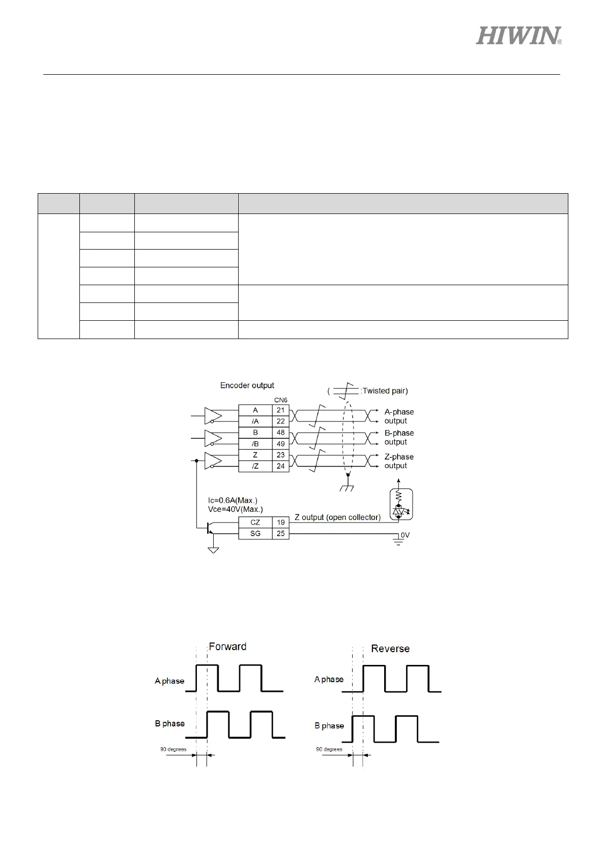
Type Signal CN6 Pin Description
Output
A 21
Differential signal with 90 degrees phase difference (A phase + B
phase) which indicates the movement of motor
/A 22
B 48
/B 49
Z 23
One Z-phase signal is output per one revolution.
/Z 24
CZ 19 One Z-phase signal is output per one revolution. (Single-ended signal)
Wiring for encoder pulse output
Figure8.6.1.1
Moving direction of motor
When A phase leads B phase, it means the motor is moving in forward direction. When B phase
leads A phase, it means the motor is moving in reverse direction.
Figure8.6.1.2

 Loading...


