E1 Series Servo Drive User Manual Application Function
HIWIN MIKROSYSTEM CORP. 8-73
Table8.12.1
Type Signal Hardware Pin Status Description
Input MAP
Edge-triggered Servo drive error map input signal
(2) Using the internal homing procedure of the servo drive
Perform internal homing procedure by referring to section 8.11.
Related parameters
Set to perform error map function on which axis by Pt009= t.X.
Table8.12.2
Parameter Description Effective Category
Pt009
t.0
(Default)
Enable error map function for single axis.
After power on Setup
t.1 Enable error map function for gantry axes.
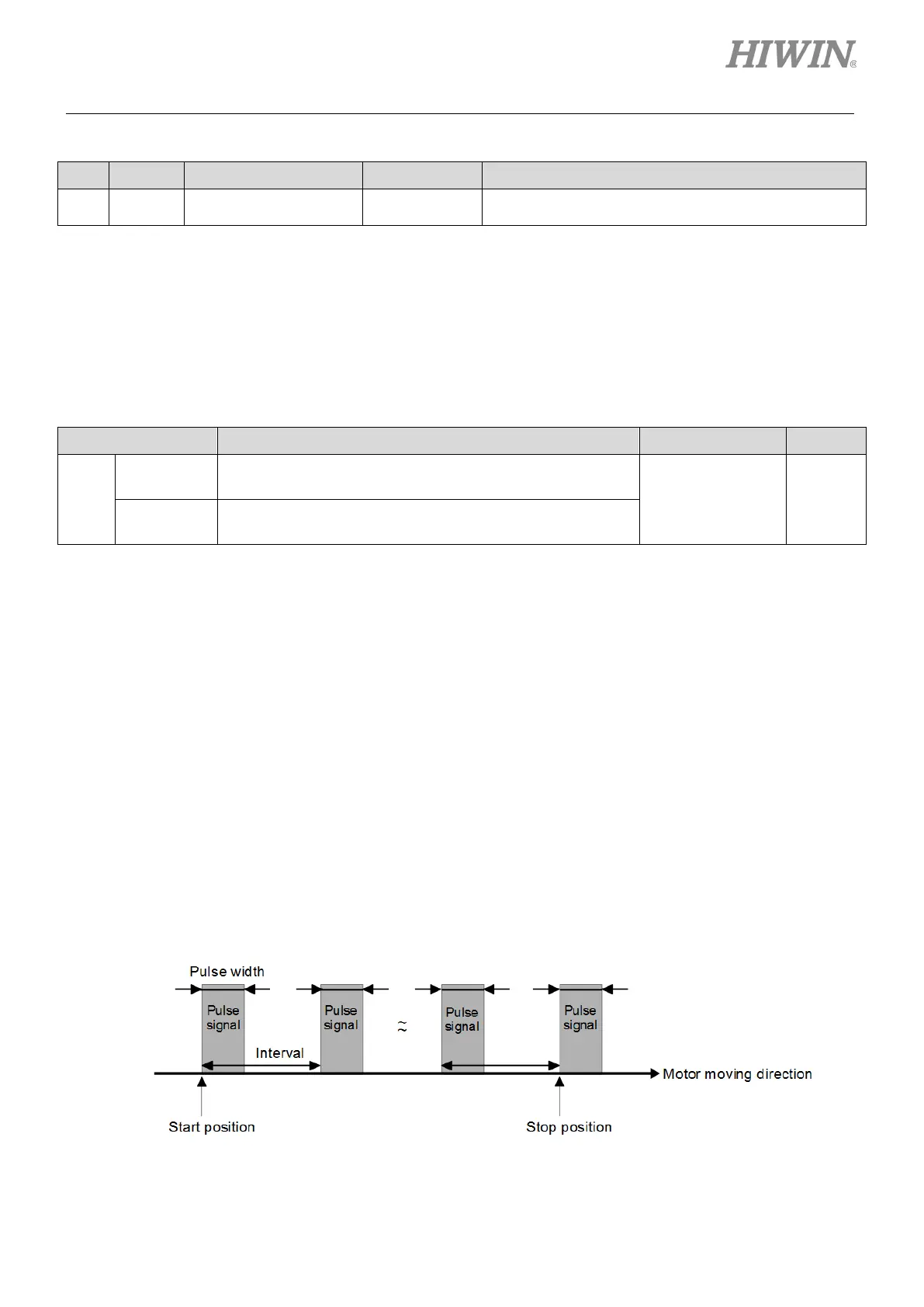
8.13 Setting position trigger function
E1 series servo drive provides position trigger (PT) function. When motor moves to the set position, the
servo drive simultaneously outputs a pulse signal. The width and interval of the pulse signal can be
user-defined, as figure 8.13.1. Position trigger function has no human machine interface, so its related
parameters must be set via PDL or MPI. The hardware pins for position trigger digital output (PT) signal
are CN6 46 and 47 (3.3 V). The signal can be allocated to digital outputs O1~O5 (24 V), if users cannot
support such voltage level. Position trigger (PT) function is mainly used in application which requires
simultaneous in-position signal for high-speed and high-precision processing, such as laser equipment,
line scan camera and lithography equipment.
Figure8.13.1

 Loading...


