E1 Series Servo Drive User Manual Application Function
HIWIN MIKROSYSTEM CORP. 8-33
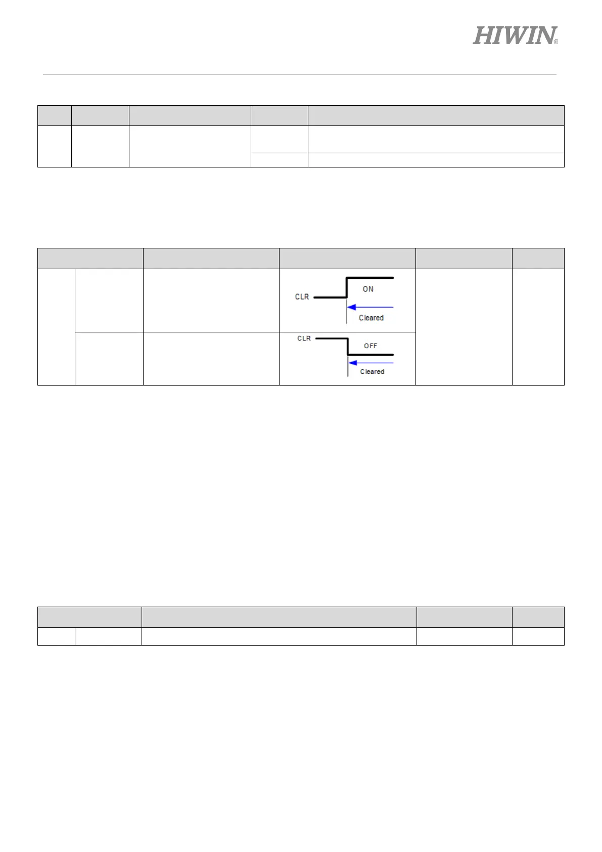
Table8.4.7.1
Type Signal Hardware Pin Status Description
Input CLR User-defined
ON
Position deviation clear input (CLR) signal is input and
the deviation counter is 0.
Start to count position deviation.
Setting position deviation clear input (CLR) signal
CLR signal is set by Pt200 = t.X (Clear signal form).
Table8.4.7.2
Parameter Control Mode Input Signal Effective Category
Pt200
t.0
(Default)
when the input signal is at
high level.
After power on Setup
t.1
when the input signal is at
low level.
Note:
The width of CLR signal must satisfy the following condition:
If Pt200 = t.X is 0 or 1, the signal width must be larger than 0.5 ms to ensure the signal is received by the
servo drive.
8.5 Torque mode
In torque mode, motor torque or force is controlled by analog command (analog voltage). Set Pt000 to
t.2 to select torque mode.
Table8.5.1
Parameter Description Effective Category
Pt000 t.2 Control mode: torque mode After power on Setup

 Loading...


