1D-24 Engine Mechanical:
• After remounting the engine, route the wiring harness,
cable and hoses properly. Refer to “Wiring Harness
Routing Diagram (GSF650/S/A/SAK7) in Section 9A
(Page 9A-8)”, “Throttle Cable Routing Diagram
(GSF650/S/A/SAK7) (Page 1D-2)” and “Water Hose
Routing Diagram in Section 1F (Page 1F-3)”.
• Pour engine coolant and engine oil. Refer to “Cooling
System Inspection in Section 0B (Page 0B-14)” and
“Engine Oil and Filter Replacement in Section 0B
(Page 0B-12)”.
• After finishing the engine installation, check the
following items.
– Throttle cable play
Refer to “Throttle Cable Play Inspection and
Adjustment in Section 0B (Page 0B-14)”
– Throttle valve synchronization
Refer to “Throttle Valve Synchronization (Page 1D-
16)”.
– Drive chain slack
Refer to “Drive Chain Inspection and Adjustment in
Section 0B (Page 0B-17)”.
– Engine oil and coolant leakage
Refer to “Cooling System Inspection in Section 0B
(Page 0B-14)”.
Engine Top Side Disassembly
B817H21406016
It is unnecessary to remove the engine assembly from
the frame when servicing the engine top side.
NOTE
Before servicing the engine top side, remove
the fuel tank, thermostat connector, PAIR
control solenoid valve, ignition coil/plug cap,
throttle body assembly, exhaust pipes,
muffler, radiator and etc. Refer to “Engine
Assembly Removal (Page 1D-18)”.
CAUTION
!
Identify the position of each removed part.
Organize the parts in their respective groups
(e.g., intake, exhaust) so that they can be
reinstalled in their original positions.
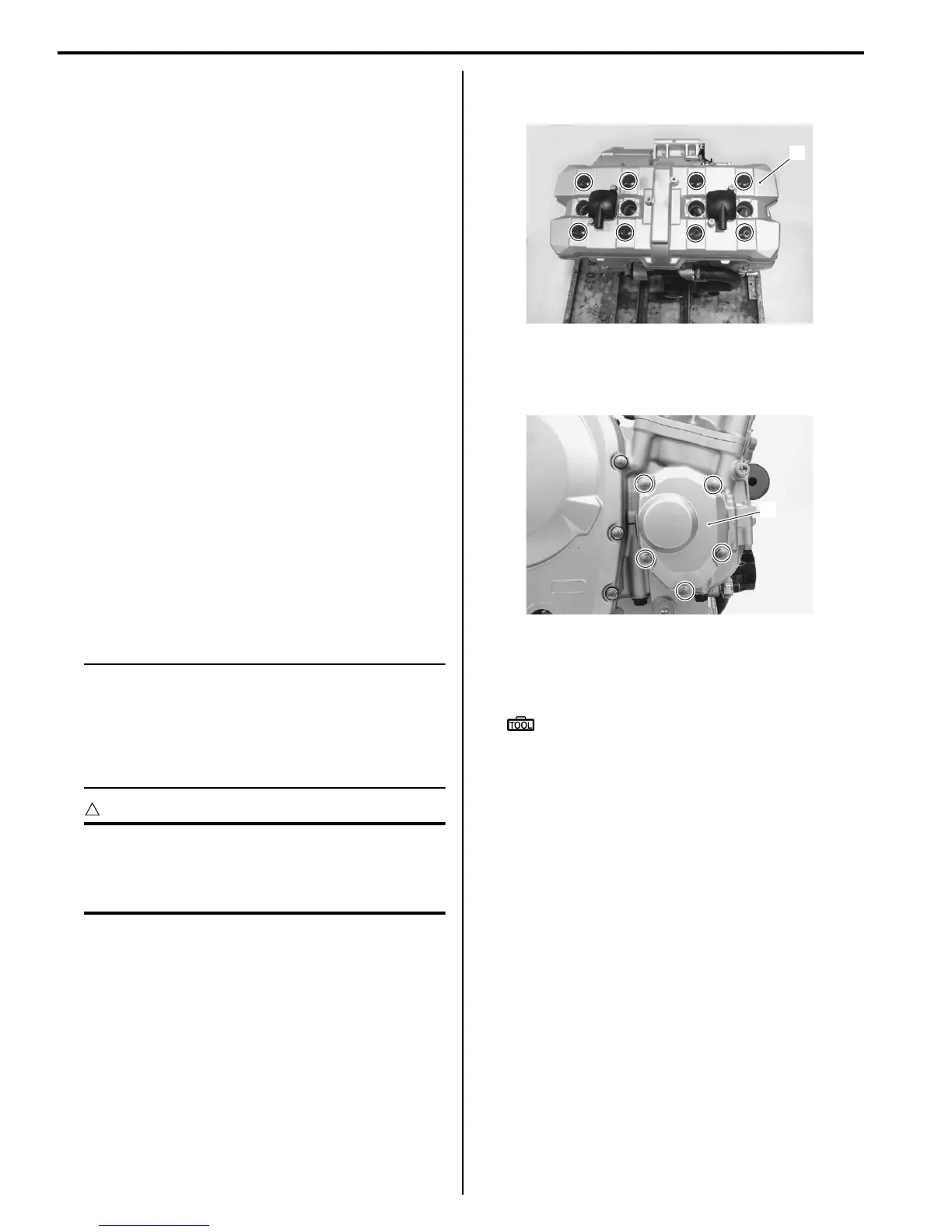
Cylinder Head Cover
Remove the cylinder head cover (1) and its gasket.
Camshaft
1) Remove the right crankshaft cover (1) and its gasket.
2) Remove all of the spark plugs. Refer to “Ignition Coil
/ Plug Cap and Spark Plug Removal and Installation
in Section 1H (Page 1H-3)”.
Special tool
: 09930–10121 (Spark plug wrench set)
1
I717H1140064-01
1
I717H1140065-01
 Loading...


