1D-34 Engine Mechanical:
Cylinder Head Cover Inspection
B817H21406019
Inspect the cylinder head cover in the following
procedures:
1) Remove the cylinder head cover. Refer to “Engine
Top Side Disassembly (Page 1D-24)”.
2) Clean and check the gasket grooves “A” and PAIR
reed valve gasket mating surfaces “B” of cylinder
head cover.
If it is damaged, replace the cylinder head cover with
a new one.
3) Install the cylinder head cover. Refer to “Engine Top
Side Assembly (Page 1D-26)”.
Camshaft Inspection
B817H21406020
Refer to “Engine Top Side Disassembly (Page 1D-24)”.
Refer to “Engine Top Side Assembly (Page 1D-26)”.
Camshaft Identification
The exhaust camshaft has the embossed letters “EX”
and the intake camshaft has the embossed letters “IN”.
Cam Wear
Check the camshaft for wear or damage.
Measure the cam height “a” with a micrometer.
Replace a camshaft if the cams are worn to the service
limit.
Special tool
: 09900–20202 (Micrometer (1/100 mm, 25 – 50
mm))
Cam height “a”
Service limit: (IN) 35.35 mm (1.3917 in)
Service limit: (EX) 35.07 mm (1.3807 in)
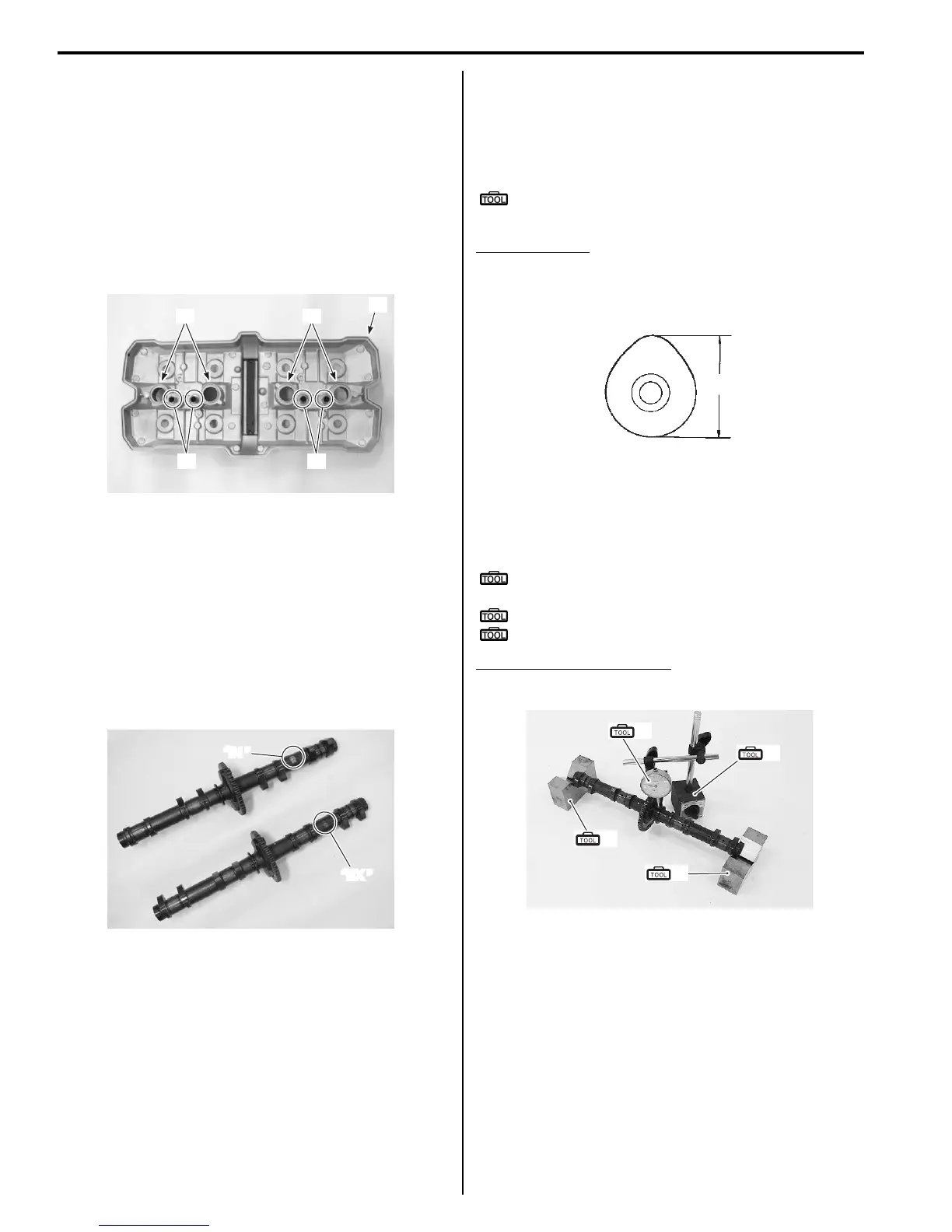
Camshaft Runout
Measure the runout using the dial gauge. Replace the
camshaft if the runout exceeds the limit.
Special tool
(A): 09900–20607 (Dial gauge (1/100 mm, 10
mm))
(B): 09900–20701 (Magnetic stand)
(C): 09900–21304 (V-block (100 mm))
Camshaft runout (IN & EX)
Service limit: 0.10 mm (0.004 in)
Camshaft Journal Wear
Inspect the camshaft journal wear in the following
procedures:
1) Determine whether or not each journal is worn down
to the limit by measuring the oil clearance with the
camshaft installed in place.
“A” “A”
“B” “B”
“A”
I717H1140099-01
“IN ”
“EX ”
I717H1140100-01
“a”
I649G1140199-02
(A)
(B)
(C)
(C)
I718H1140082-01
 Loading...


