5B-14 Manual Transmission:
Gearshift lever Removal and Installation
B817H25206010
Removal
1) Place the motorcycle on the center stand.
2) Remove the gearshift lever as shown in the gearshift
lever construction. Refer to “Gearshift lever
Construction (Page 5B-13)”.
Installation
1) Install the gearshift lever as shown in the gearshift
lever construction. Refer to “Gearshift lever
Construction (Page 5B-13)”.
2) After installing the gearshift lever, check the gearshift
lever height. Refer to “Gearshift Lever Height
Inspection and Adjustment (Page 5B-14)”.
Gearshift Lever Height Inspection and
Adjustment
B817H25206011
Inspect and adjust the gearshift lever height in the
following procedures:
1) Inspect the gearshift lever height “a” between the
pedal top face and footrest.
Adjust the gearshift lever height if necessary.
Gearshift lever height “a”
Standard: 45 – 55 mm (1.8 – 2.2 in.)
2) Loosen the lock-nuts (1).
3) Turn the gearshift link rod (2) until the gearshift lever
is 45 – 55 mm (1.8 – 2.2 in.) below the top of the
footrest.
4) Tighten the lock-nuts securely.
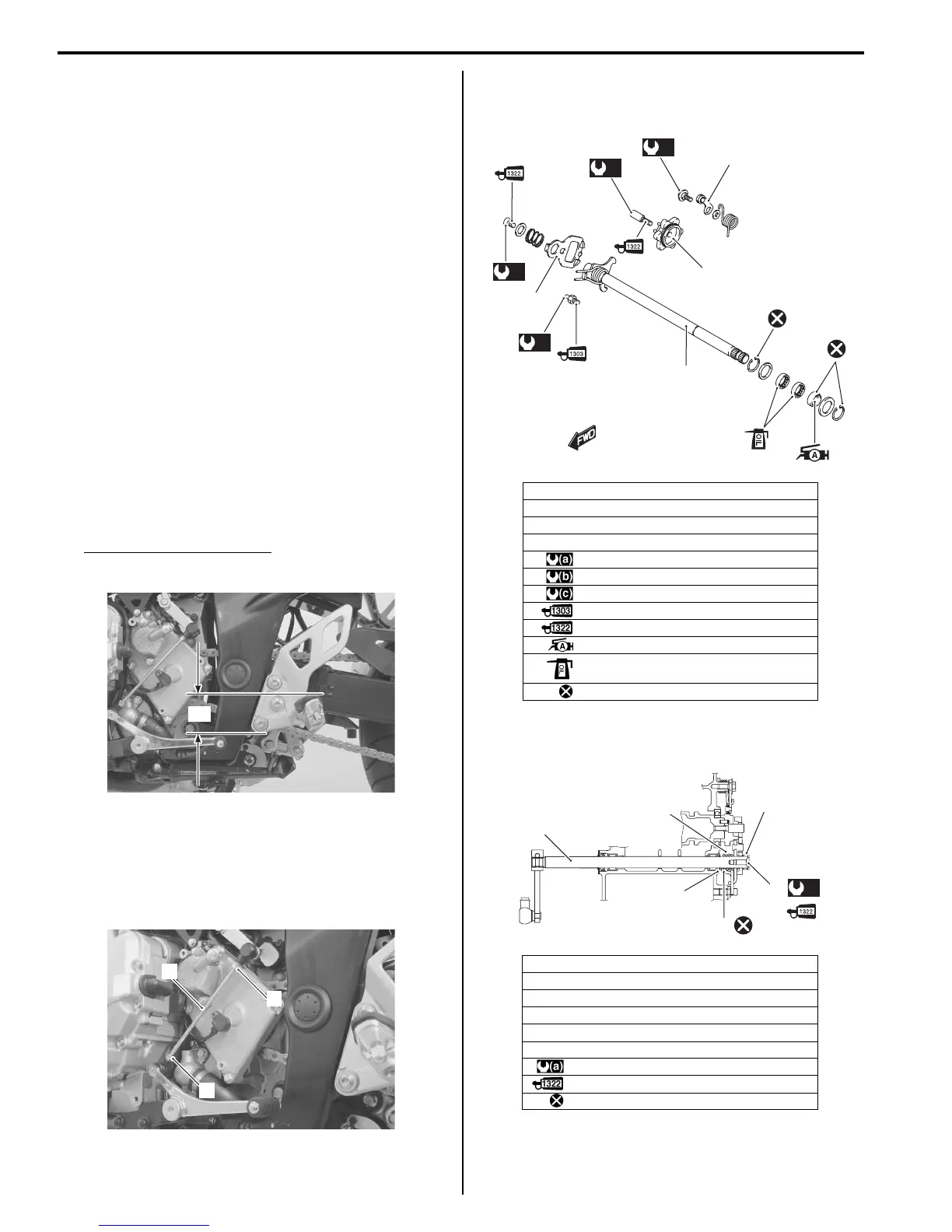
Gearshift Shaft / Gearshift Cam Plate
Components
B817H25206012
Gearshift Construction
B817H25206013
“a”
I717H1520019-01
1
1
2
I717H1520020-02
1. Gearshift shaft
2. Gearshift cam drive plate
3. Gearshift cam plate
4. Gearshift cam stopper
:10 N⋅m (1.0 kgf-m, 7.0 lb-ft)
:13 N⋅m (1.3 kgf-m, 9.5 lb-ft)
:19 N⋅m (1.9 kgf-m, 13.5 lb-ft)
: Apply thread lock to thread part.
: Apply thread lock to thread part.
: Apply grease to oil seal lip.
: Apply engine oil.
: Do not reuse.
1. Gearshift shaft
2. Washer
3. Snap ring
4. Gearshift shaft return spring
5. Gearshift plate return spring
6. Gearshift shaft end bolt
: 10 N⋅m (1.0 kgf-m, 7.0 lb-ft)
: Apply thread lock to thread part.
: Do not reuse.
1
(c)
2
(a)
(b)
(a)
4
3
I718H1520075-03
(a)
1
2
3
5
6
4
I718H1520002-02
 Loading...


