1H-6 Ignition System:
CKP Sensor Inspection
B817H21806004
Refer to “Electrical Components Location in Section 0A
(Page 0A-10)”.
CKP Sensor Peak Voltage
1) Disconnect the CKP sensor coupler (1).
NOTE
Be sure that all of the couplers are connected
properly and the battery is fully-charged.
2) Connect the multi-circuit tester with the peak volt
adaptor as follows.
CAUTION
!
Before using the multi-circuit tester and peak
voltage adaptor, refer to the appropriate
instruction manual.
Special tool
(A): 09900–25008 (Multi-circuit tester set)
Tester knob indication: Voltage ( )
3) Measure the CKP sensor peak voltage in the
following procedure.
a) Shift the transmission into neutral, turn the
ignition switch ON and grasp the clutch lever.
b) Press the starter button and allow the engine to
crank for a few seconds, and then measure the
CKP sensor peak voltage.
4) Repeat the b) procedure a few times and measure
the highest CKP sensor peak voltage.
CKP sensor peak voltage
2.0 V and more (B/BI – Y/W)
5) If the peak voltage is within the specification, check
the continuity between the CKP sensor coupler and
ECM coupler.
CAUTION
!
Normally, use the needle pointed probe to the
backside of the lead wire coupler to prevent
the terminal bend and terminal alignment.
6) After measuring the CKP sensor peak voltage,
connect the CKP sensor coupler.
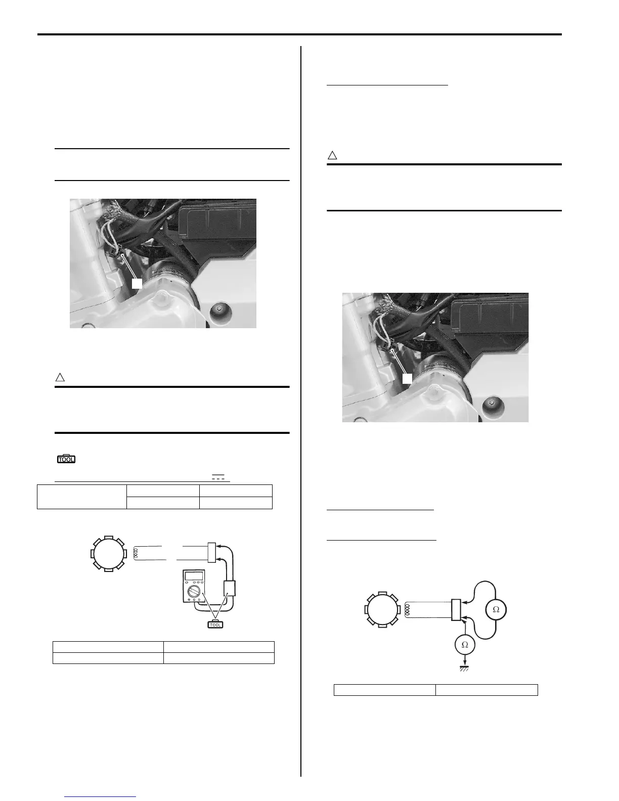
CKP Sensor Resistance
1) Disconnect the CKP sensor coupler (1).
2) Measure the resistance between the lead wires and
ground. If the resistance is not within the standard
range, replace the CKP sensor with a new one.
Refer to “CKP Sensor Removal and Installation
(Page 1H-7)”.
Tester knob indication
Resistance (Ω)
CKP sensor resistance
Approx. 90 – 150 Ω (Bl/Y – Green)
∞ Ω (Bl/Y – Ground)
3) After measuring the CKP sensor resistance, connect
the CKP sensor coupler.
Ignitor coupler
(+) Probe (–) Probe
BI/Y G
2. CKP sensor coupler 4. Peak voltage adaptor
3. CKP sensor
1
I717H1180006-01
2
3
G
BI/Y
(A)
4
I718H1180007-02
2. CKP sensor coupler 3. CKP sensor
1
I717H1180007-01
3
2
I718H1180008-02
 Loading...


