2D-17 Wheels and Tires:
Air Valve Removal and Installation
B817H22406013
Removal
1) Remove the wheel assembly. Refer to “Front Wheel
Assembly Removal and Installation (GSF650/S/U/
SUK7) (Page 2D-4)” and “Rear Wheel Assembly
Removal and Installation (GSF650/S/U/SUK7)
(Page 2D-11)”.
2) Remove the tire. Refer to “Tire Removal and
Installation (Page 2D-15)”.
3) Remove the air valve (1) from the wheel.
Installation
Install the air valve in the reverse order of removal. Pay
attention to the following points:
• Any dust or rust around the valve hole (1) must be
cleaned off.
• Install the air valve (2) in the wheel (3).
CAUTION
!
• Be careful not to damage the lip (4) of
valve.
• Replace the air valve with a new one.
NOTE
To properly install the valve into the valve
hole, apply a special tire lubricant or neutral
soapy liquid to the valve.
Wheel Balance Check and Adjustment
B817H22406014
Check and adjust the wheel balance in the following
procedures:
1) Removal the wheel assembly. Refer to “Front Wheel
Assembly Removal and Installation (GSF650/S/U/
SUK7) (Page 2D-4)” and “Rear Wheel Assembly
Removal and Installation (GSF650/S/U/SUK7)
(Page 2D-11)”.
2) Remove the mounting drum from the rear wheel.
Refer to “Rear Wheel Dust Seal / Bearing Removal
and Installation (Page 2D-13)”.
3) Check the wheel balance using the balancer and
adjust the wheel balance if necessary.
CAUTION
!
For operating procedures, refer to the
instructions supplied by the wheel balancer
manufacturer.
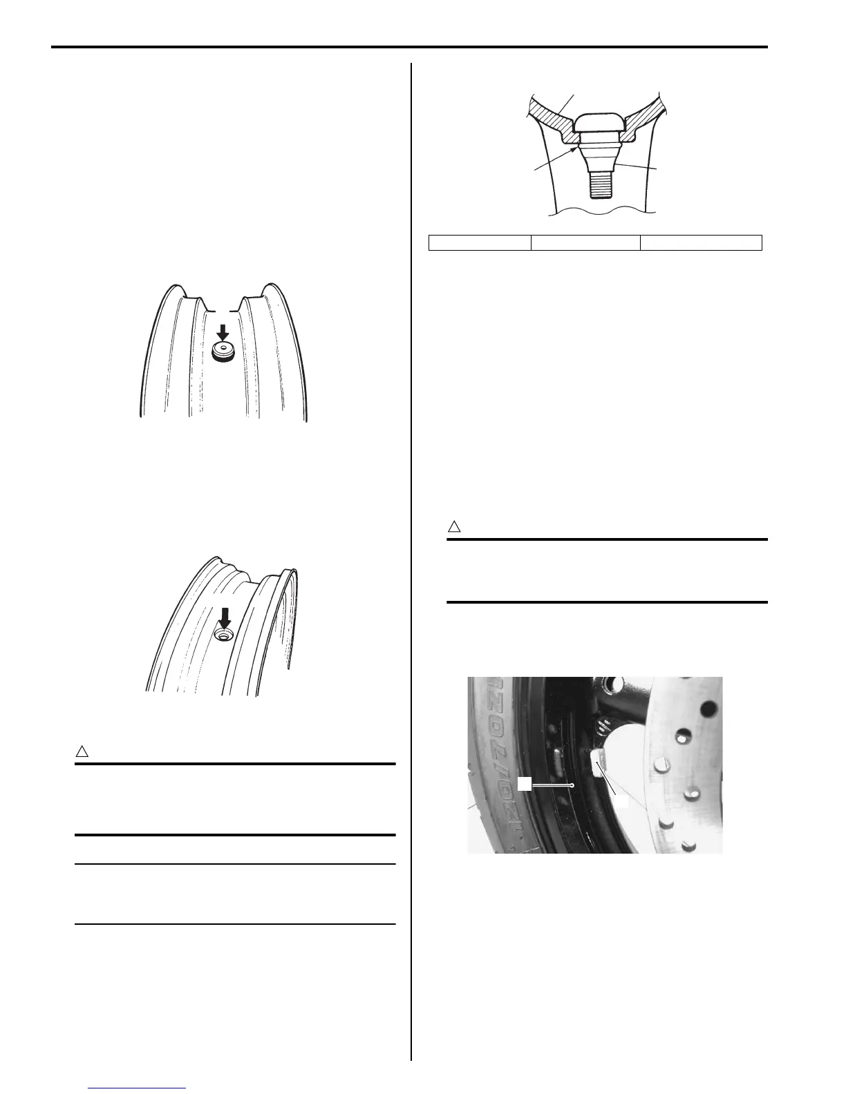
4) When installing the balancer weight (1) to the wheel
(2), set the balancer weight on center rib of the
wheel.
5) Recheck the wheel balance.
6) Install the mounting drum to the rear wheel. (For rear
wheel)
Refer to “Rear Wheel Dust Seal / Bearing Removal
and Installation (Page 2D-13)”.
7) Install the wheel assembly. Refer to “Front Wheel
Assembly Removal and Installation (GSF650/S/U/
SUK7) (Page 2D-4)” and “Rear Wheel Assembly
Removal and Installation (GSF650/S/U/SUK7)
(Page 2D-11)”.
1
I649G1240046-02
1
I718H1240054-01
2. Valve 3. Wheel 4. Valve lip
3
2
4
I718H1240055-01
1
2
I717H1240038-01
 Loading...


