Wheels and Tires: 2D-12
3) Adjust the drive chain slack after installing the rear
wheel. Refer to “Drive Chain Inspection and
Adjustment in Section 0B (Page 0B-17)”.
4) Tighten the rear axle nut (3) to the specified torque.
Tightening torque
Rear axle nut (a): 100 N·m (10.0 kgf-m, 72.5 lbf-
ft)
WARNING
!
After remounting the rear wheel, pump the
brake pedal a few times to check for proper
brake operation.
Rear Wheel Related Parts Inspection
B817H22406009
Refer to “Rear Wheel Assembly Removal and
Installation (GSF650/S/U/SUK7) (Page 2D-11)”.
Tire
Refer to “Tire Inspection in Section 0B (Page 0B-20)”.
Rear Brake Disc
Refer to “Rear Brake Disc Inspection in Section 4C
(Page 4C-7)”.
Wheel Damper
Refer to “Drive Chain Related Components in Section
3A (Page 3A-1)”.
Sprocket
Refer to “Drive Chain Related Parts Inspection in
Section 3A (Page 3A-5)”.
Dust Seal
Inspect the dust seal lip for wear or damage. If any
defects is found, replace the dust seal with a new one.
Refer to “Rear Wheel Dust Seal / Bearing Removal and
Installation (Page 2D-13)”.
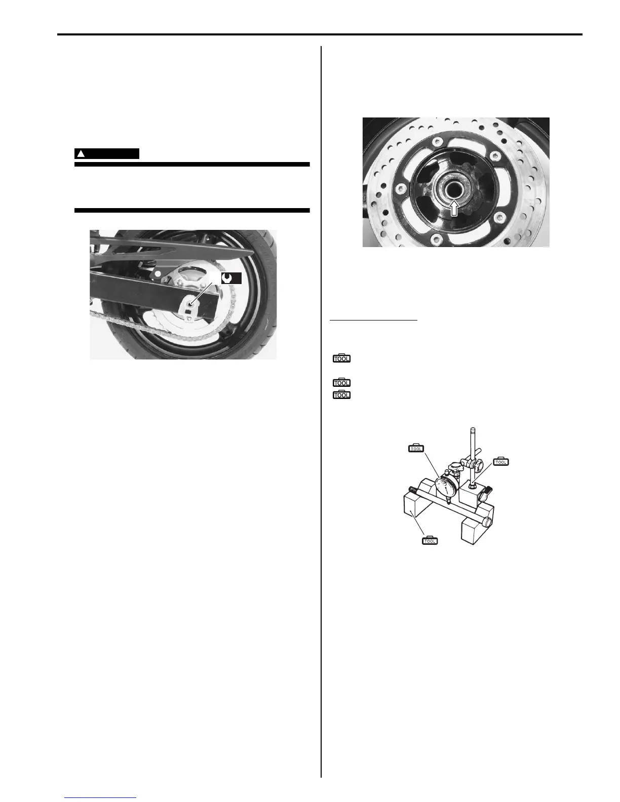
Wheel Axle
Using a dial gauge, check the wheel axle for runout, If
the runout exceeds the limit, replace the axle shaft.
Wheel axle runout
Service limit: 0.25 mm (0.010 in.)
Special tool
(A): 09900–20607 (Dial gauge (1/100 mm, 10
mm))
(B): 09900–20701 (Magnetic stand)
(C): 09900–21304 (V-block (100 mm))
Wheel
Inspect the wheel in the following procedures:
1) Remove the brake pads. Refer to “Rear Brake Pad
Replacement in Section 4C (Page 4C-2)”.
2) Make sure that the wheel runout checked as shown
does not exceed the service limit. An excessive
runout is usually due to worn or loosened wheel
bearings and can be reduced by replacing the
bearings. If bearing replacement fails to reduce the
runout, replace the wheel.
(a)
3
I717H1240028-01
I717H1240029-01
(A)
(B)
(C)
I649G1230034-03
 Loading...


