Clutch: 5C-10
4) Remove the clutch release cylinder (3).
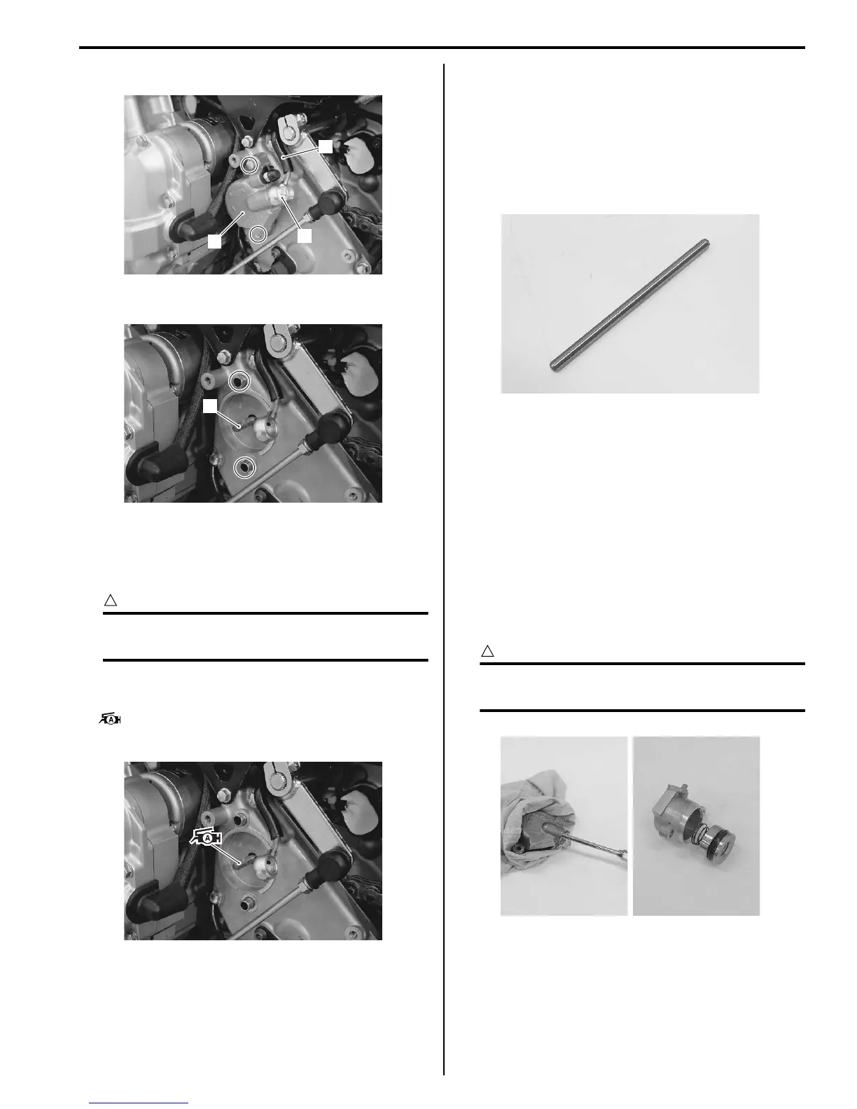
5) Remove the dowel pins and push rod (4).
Installation
Install the clutch release cylinder in the reverse order of
removal. Pay attention to the following points:
CAUTION
!
The seal washers should be replaced with the
new ones to prevent fluid leakage.
• Apply a small quantity of GREASE “A” to the push
rod.
: Grease 99000–25010 (SUZUKI SUPER
GREASE A or equivalent)
• Install the clutch hose as shown in the clutch hose
routing diagram. Refer to “Clutch Hose Routing
Diagram (Page 5C-2)”.
• Bleed air from the clutch system. Refer to “Air
Bleeding from Clutch Fluid Circuit (Page 5C-3)”.
Clutch Push Rod (Left) Inspection
B817H25306012
Inspect the push rod in the following procedures:
1) Remove the clutch push rod. Refer to “Clutch
Release Cylinder / Push Rod Removal and
Installation (Page 5C-9)”.
2) Inspect the push rod for wear or bend. If any defects
are found, replace it with a new one.
3) Reinstall the removed parts. Refer to “Clutch
Release Cylinder / Push Rod Removal and
Installation (Page 5C-9)”.
Clutch Release Cylinder Disassembly and
Assembly
B817H25306013
Refer to “Clutch Release Cylinder / Push Rod Removal
and Installation (Page 5C-9)”.
Disassembly
1) Place a rag over the piston to prevent popping up.
2) Force out the piston by using air gun.
CAUTION
!
Do not use high pressure air to prevent
piston damage.
1
2
3
I717H1530032-01
4
I717H1530033-01
I717H1530034-01
I718H1530025-01
I718H1530026-01
 Loading...


