Engine Cooling System: 1F-9
3) First check the insulation between “A” and “B”
terminals with tester. Then apply 12 volts to “C” and
“D” terminals, (+) to “C” and (–) to “D”, and check the
continuity between “A” and “B”.
If there is no continuity, replace it with a new one.
Special tool
: 09900–25008 (Multi-circuit tester set)
Tester knob indication set
Continuity test ( )
4) Reinstall the removed parts.
ECT Sensor Removal and Installation
B817H21606011
Refer to “ECT Sensor Removal and Installation in
Section 1C (Page 1C-2)”.
ECT Sensor Inspection
B817H21606012
Refer to “ECT Sensor Inspection in Section 1C
(Page 1C-3)”.
Thermostat Connector / Thermostat Removal
and Installation
B817H21606013
Removal
1) Drain a small amount of engine coolant. Refer to
“Cooling System Inspection in Section 0B (Page 0B-
14)”.
2) Remove the fuel tank. Refer to “Fuel Tank Removal
and Installation in Section 1G (Page 1G-9)”.
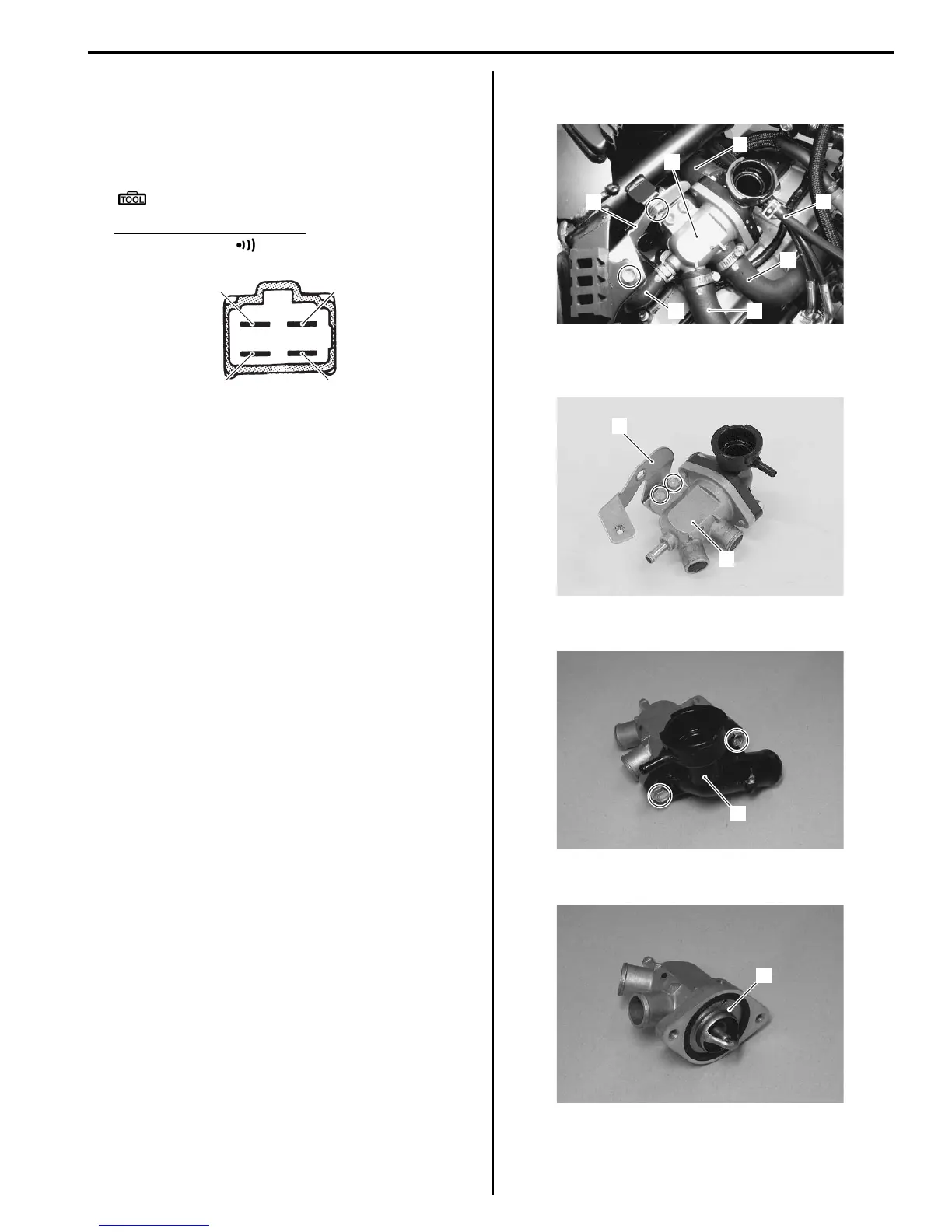
3) Disconnect the following parts from the thermostat
connector (1).
• Water bypass hose (2)
• Cylinder outlet left hose (3)
• Cylinder outlet right hose (4)
• Radiator inlet hose (5)
• Reservoir tank inlet hose (6)
4) Remove the thermostat connector (1) along with
bracket (7).
5) Remove the bracket (7) from the thermostat
connector (1).
6) Remove the connector cap (8).
7) Remove the thermostat (9).
“A”
“B”
“C”
“D”
I718H1160006-03
1
2
3
5
6
7
4
I717H1160017-01
1
7
I718H1160060-01
8
I718H1160049-01
9
I718H1160050-01
 Loading...


