Combination Meter / Fuel Meter / Horn: 9C-10
Installation
Install the speed sensor in the reverse order of removal.
Pay attention to the following points:
• Tighten the speed sensor mounting bolt to the
specified torque.
Tightening torque
Speed sensor bolt (a): 6.5 N·m (0.65 kgf-m, 4.7
lbf-ft)
• Route the speed sensor lead wire. Refer to “Wiring
Harness Routing Diagram (GSF650/S/A/SAK7) in
Section 9A (Page 9A-8)”.
Speed Sensor Inspection
B817H29306012
Inspect the speed sensor in the following procedures:
1) Remove the speed sensor. Refer to “Speed Sensor
Removal and Installation (Page 9C-9)”.
2) Connect a 12 V battery (between B and B/W), 10 kΩ
resistor (between B/R and B) and multi-circuit tester
(tester (+) probe to B and tester (–) probe to B/R) as
shown.
Special tool
: 09900–25008 (Multi-circuit tester set)
Tester knob indication
Voltage ( )
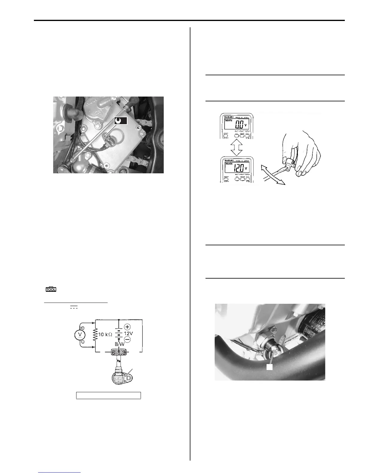
3) Move a screwdriver back and forth across the pick-
up surface of the speed sensor. The voltage
readings should cycle as follows (0 V → 12 V or 12 V
→ 0 V). If the voltage reading does not change,
replace the speed sensor with a new one.
NOTE
While testing, the highest voltage reading
should be the same as the battery voltage (12
V).
Oil Pressure Indicator Inspection (GSF650/S/A/
SAK7)
B817H29306013
Inspect the oil pressure indicator in the following
procedures:
NOTE
Before inspecting the oil pressure switch,
check if the engine oil level is correct. Refer
to “Engine Oil and Filter Replacement in
Section 0B (Page 0B-12)”.
1) Disconnect the oil pressure switch lead wire (1) from
the oil pressure switch.
1. Speed sensor
(a)
I718H1930044-03
B
1
B/R
I717H1930018-01
I649G1930017-02
1
I717H1930013-01
 Loading...


