3 - 5
Operation panel
Main unit
Assembly
4
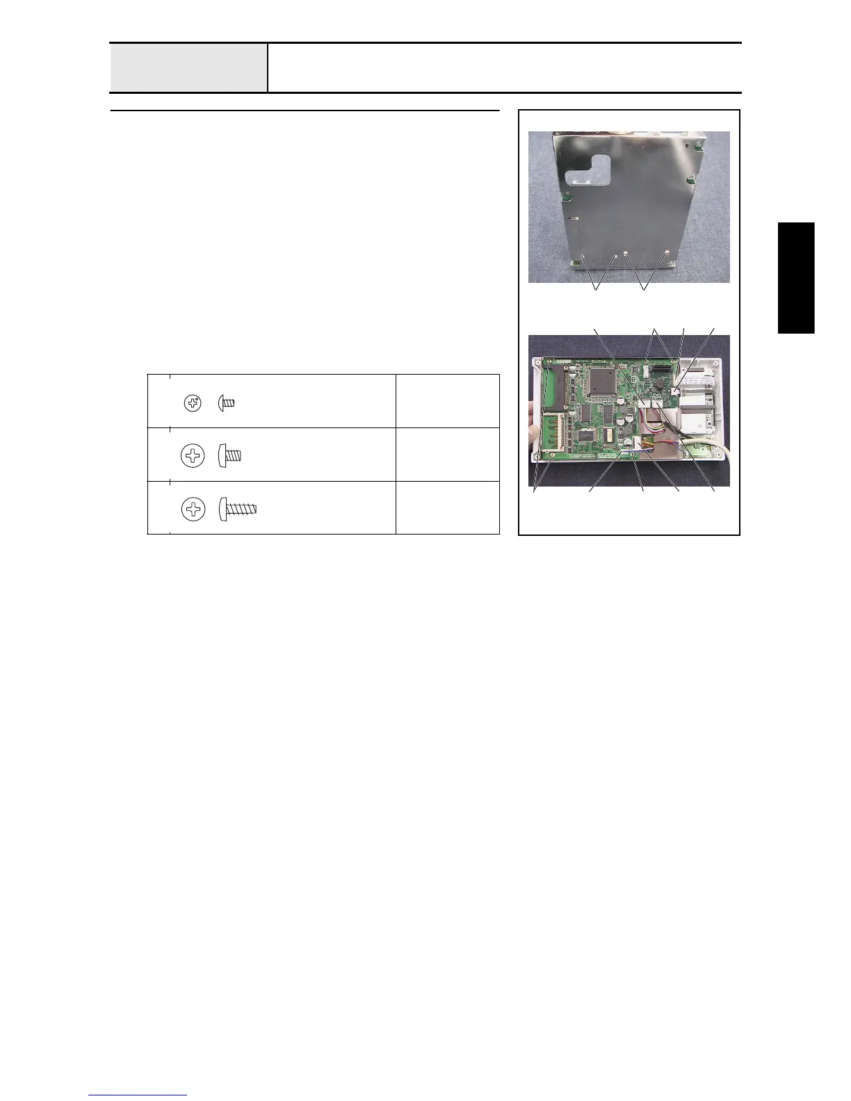
Panel PCB assembly attachment
1. Attach the panel PCB assembly to board case A with the 4 screws (1 2, 2
each).
2. Attach board case A and the panel PCB assembly to the operation panel A
assembly with the 5 screws 3.
3. Connect the switch PCB assembly's lead wire 1, inverter lead wire
assembly 2, LCD cable 3, and touch panel's lead wire 4 to the panel
PCB assembly.
*Key point
• Be sure to lock the connectors after the touch panel's lead
wire and the LCD cable have been connected to the panel
PCB.
4. Connect the USB lead wire assembly A 5 and the panel lead wire
assembly A 6 to the panel PCB assembly.
1
Torque
0.29 –
0.49 N-m
2
Torque
0.78 –
1.18 N-m
3
Torque
0.39 –
0.78 N-m
1 2
1 3
3 32 6 5
3
4
Screw, Truss
M2X3
Color; Silver
Screw, Bind
M3X3
Color; Silver
Taptite, Bind B
M3X8
Color; Gold

 Loading...