2 - 56
Main unit
Power unit
1
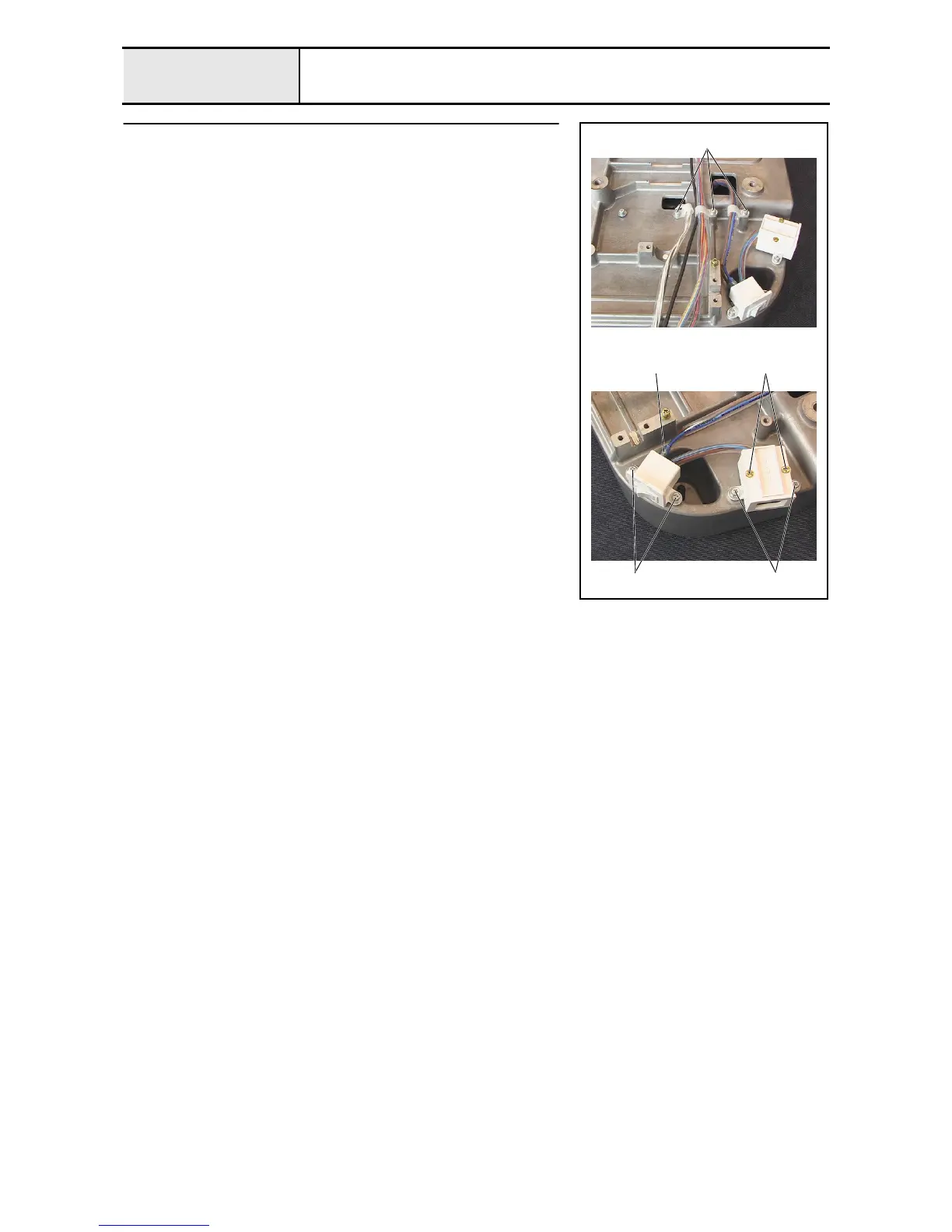
Power switch assembly and inlet removal
1. Remove the 3 screws 1 and the 3 cord clamps (NK-6N), and then remove
the power PCB assembly's lead wire, USB lead wire assembly, Y-area
sensor assembly's lead wire, and power unit lead wire assembly from the
base frame.
2. Remove the 2 screws 2 and remove the inlet cover lid, and then remove
the rocker switch on the power switch assembly from the inlet cover.
3. Remove the 2 screws 3, and then remove the inlet cover.
4. Remove the 2 screws 4, and then remove the power switch assembly.
5. Remove the 2 power lead wire assemblies 1 from the power switch
assembly.
1
1
2
34

 Loading...