3 - 83
Feed unit
Main unit
Assembly
9
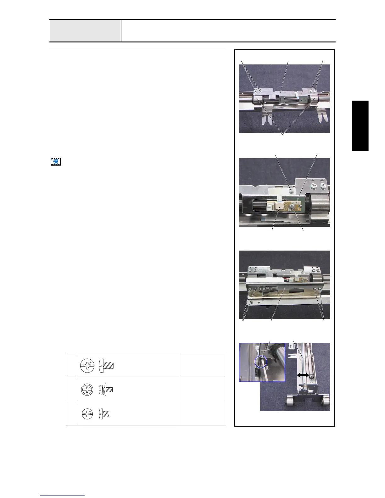
X-carriage A assembly and X-carriage B assembly attachment
1. Attach the X-carriage B assembly 1 to the 2 bearing case X final
assemblies 2 attached to the X-shaft with the 4 screws 1.
2. Attach the hoop PCB assembly 3 to the X-carriage B assembly with the
screw 2.
3. Connect the FFC (SML2CD-X) 4 to the hoop PCB assembly, hold the
FFC (SML2CD-X) with sheet C, and then tighten the screw 3.
*Key point
• After the FFC (SML2CD-X) has been connected to the hoop
PCB assembly, lock the connector.
4. Attach the X-carriage A assembly 5 to the bearing case X final assembly
(2 locations) with the 4 screws 4.
5. Connect the hoop sensor assembly's lead wire to the hoop PCB assembly.
6. Adjust the X-guide shaft 6 back and forth so that the X-carriage A
assembly's sheet 7 contacts the feed frame.
Start movie clip (CD-ROM version only)
1
4
Torque
1.18 –
1.57 N-m
2
Torque
0.59 –
0.79 N-m
3
Torque
0.59 –
0.78 N-m
1
5
3 3
24
1 1
2
4 4
7 6
Screw, Bind
M4X6
Color; Silver
Screw, Pan (S/P washer)
M3X6
Color; Silver
Screw, Bind
M3X4
Color; Silver

 Loading...