3 - 77
Feed unit
Main unit
Assembly
3
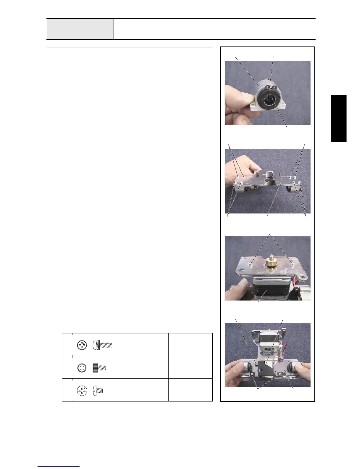
Y-carriage L assembly
1. Attach the linear bearing 10 2 to bearing case Y 1, and then attach the 2
external retaining rings C19. (2 sets)
2. Attach the 2 bearing case Y assemblies to Y-carriage L 3 with the 8
screws 1.
3. Attach the X-motor assembly 4 to Y-carriage L with the 2 screws 2.
4. Attach the caution (easy to bend) Y-carriage L with the 2 screws 3.
NOTE
• The Y sensor dog bends easily. Handle it carefully.
5. Attach the connect PCB finial assembly 5 to Y-carriage L with the 2
screws 4.
1
2
Torque
0.78 – 1.18 N-m
3
Torque
0.59 – 0.78 N-m
4
Torque
0.59 – 0.78 N-m
2
1
13
1
2
External retaining rings C19
11
4
4 5
3
4
Screw, Pan (S/P washer)
M3X10DA
Color; Gold
Bolt, Socket
M3X5
Color; Black
Screw, Bind
M3X4
Color; Silver
 Loading...