 Loading...
Do you have a question about the Brother PR600 and is the answer not in the manual?
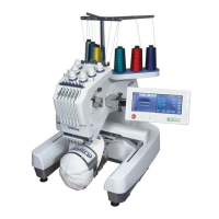
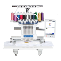
| Type | Embroidery machine |
|---|---|
| LCD Screen | Yes |
| USB Port | Yes |
| Built-in Memory | Yes |
| Connectivity | USB |
| Maximum Embroidery Area | 200mm |
| Embroidery Area | 200mm |
| Needle Count | 6 needles |
Important safety precautions to follow when handling electronic components and performing repairs.
Describes the main mechanical components of the embroidery machine.
Explains the mechanisms for power transmission and movement.
Visual representation of the machine's control system architecture and interconnections.
Explains the disassembly procedures for the main components of the machine.
Details the disassembly of the feed mechanism.
Covers the disassembly steps for the needle thread system.
Steps for disassembling the needle bar assembly.
Steps for assembling the machine's control panel and its components.
Details the assembly of the needle bar mechanism.
Explains the assembly of the feed mechanism.
Procedures for reassembling the main unit of the embroidery machine.
Important considerations and warnings before performing adjustments.
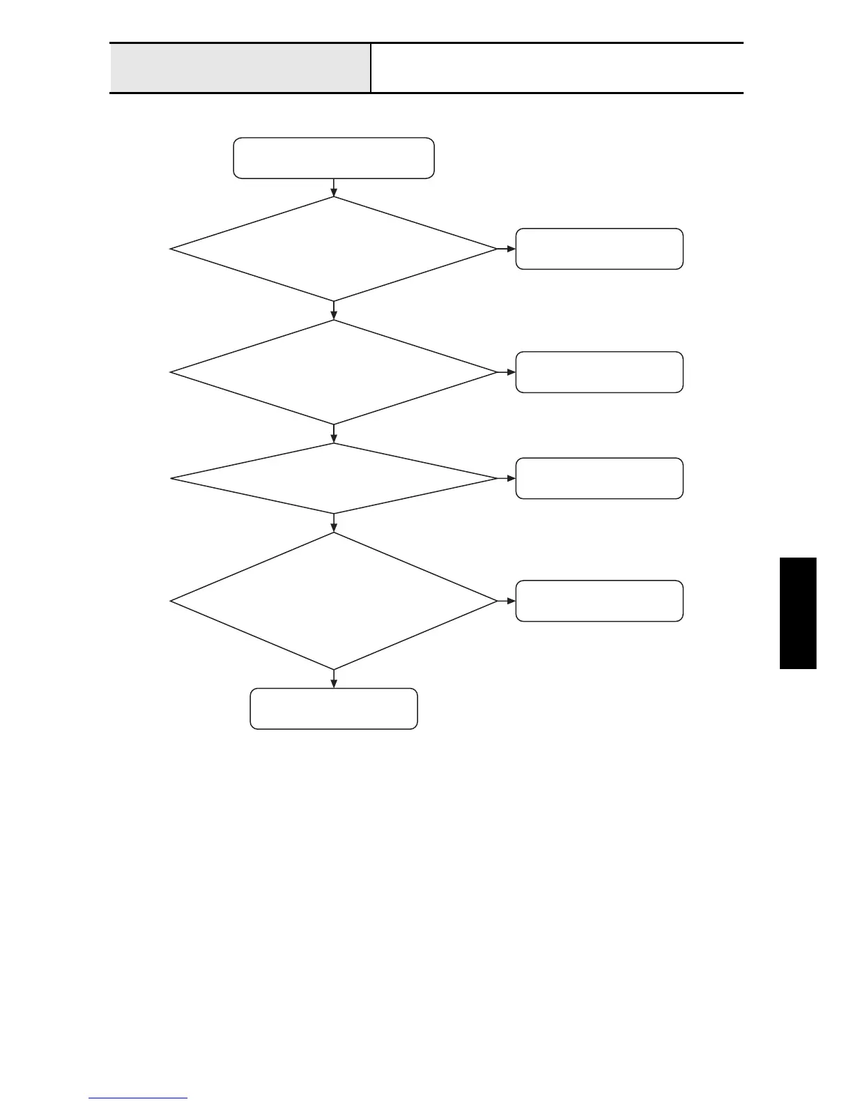
Instructions on how to enter and operate the machine's test modes for diagnostics.
Adjusting the needle's front-to-back position relative to the needle plate.
Setting the correct height for the needle bar.
A comprehensive list of error messages and their corresponding page numbers for troubleshooting.
Troubleshooting steps for when the machine does not power on.
Steps to resolve problems with hoop movement.
Diagnosing and resolving issues with needle bar movement.