3 - 30
Power unit
Main unit
4
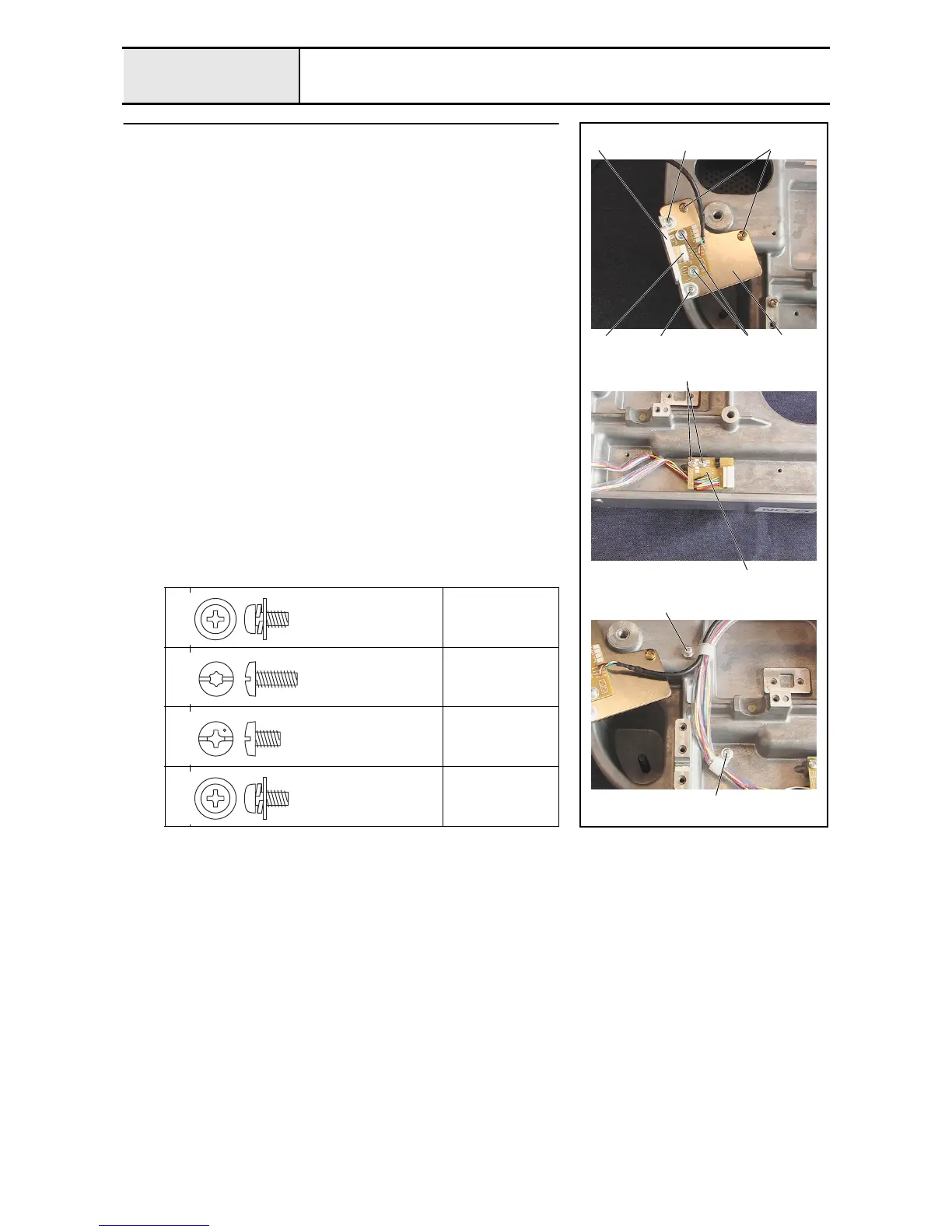
USB PCB assembly and Y-area sensor assembly attachment
1. Attach the USB PCB assembly 2 to the USB PCB holder 1 with the 2
screws 1.
2. Attach the USB PCB cover 3 to the USB PCB holder assembly with the 2
screws 2.
3. Attach the USB PCB holder assembly to the base frame with the 2 screws
3.
4.
Attach the Y-area sensor assembly
4
to the base frame with the 2 screws
4
.
5. Attach the Y-area sensor's lead wire to the base frame with the screw 5
and the cord clamp (NK-6N).
6. Attach the USB PCB assembly's lead wire and the Y-area sensor
assembly's lead wire to the base frame with the screw 6 and the cord
clamp (NK-6N).
1
2
Torque
0.78 –
1.18 N-m
3
Torque
1.47 –
1.96 N-m
4
Torque
1.18 –
1.96 N-m
5
6
Torque
0.78 –
1.18 N-m
3
4
6
5
4
2
2 211
3
Screw, Pan (S/P washer)
M4X8DB
Color; Silver
Taptite, Bind S
M4X10
Color; Gold
Screw, Bind
M4X6
Color; Silver
Screw, Pan (S/P washer)
M4X8DB
Color; Silver

 Loading...