3 - 6
Main unit
Operation panel
5
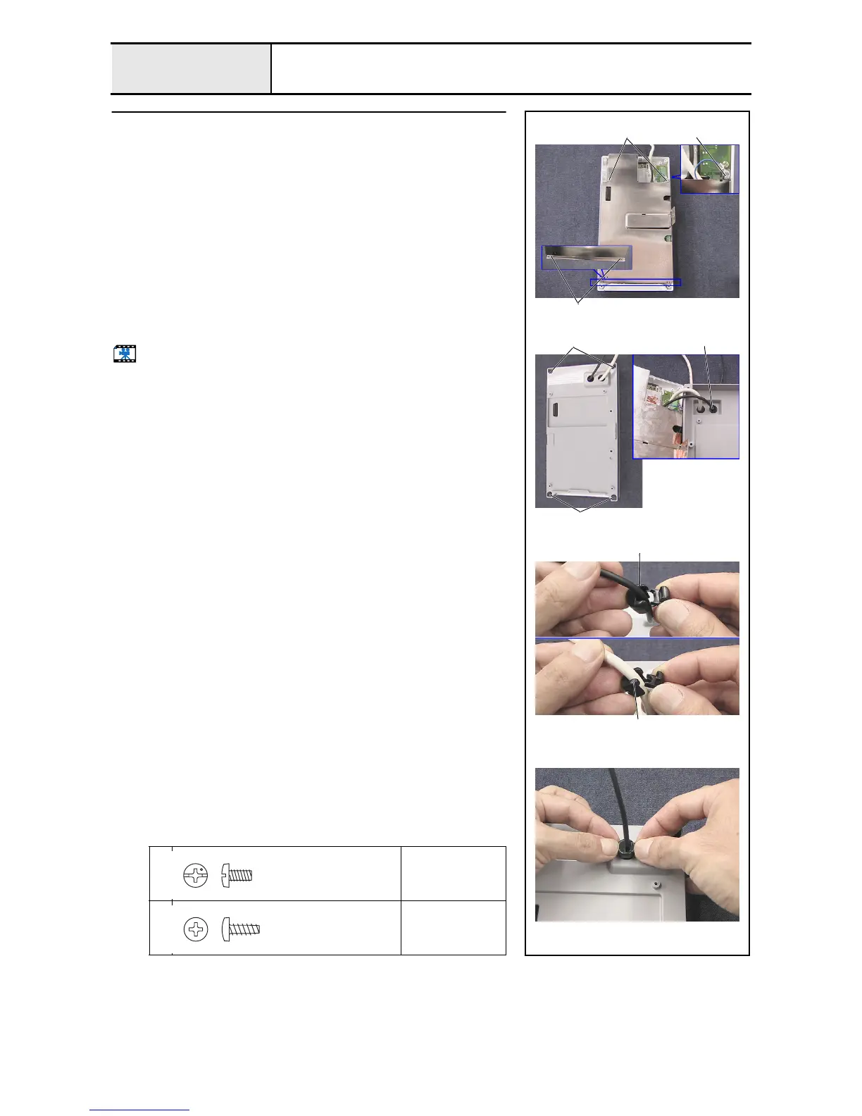
Operation panel B attachment
1. Insert the 2 lugs 1 on board case B to the corresponding holes on board
case A to attach board case B to board case A.
2. Tighten the 2 screws 1. (Tighten one of these 2 with panel lead wire
assembly A's grounding wire.)
3. Thread panel lead wire assembly A and USB lead wire assembly A
through the 2 holes 3 on operation panel B, and then attach operation
panel B to the operation panel A assembly.
4. Tighten the 4 screws 2.
5. Attach the cord bush (KF41) 4 (the section where the cord is pressed is a
straight line) to the USB lead wire assembly A, and push it into the hole on
operation panel B.
6. Attach the cord bush (KR51) 5 (the section where the cord is pressed is a
curved line) to panel lead wire assembly A, and push it into the hole on
operation panel B.
Start movie clip (CD-ROM version only)
1
Torque
0.59 –
0.78 N-m
2
Torque
0.39 –
0.78 N-m
2
2
4
5
1 2
3
3
Screw, Bind
M3X6
Color; Silver
Taptite, Bind B
M3X8
Color; Gold

 Loading...