GE MEDICAL SYSTEMS PROPRIETARY TO GE
D
IRECTION 2294854-100, REVISION 3 LOGIQ™ 9 PROPRIETARY MANUAL
5-6 Section 5-3 - Front End Processor
5-3-1Front End Processor Power Supply Board (FEPS, FEPS2, FEPS2.1) (cont’d)
The high voltage lockout circuit monitors the +5VA, -5VA, +12VA and 3V3 supplies and locks out the
PHVP supply in the event that any one of them go below 10% of their nominal value.
PWR_OK is an active high TTL compatible output which provides a status indication of the AC input
power. It should be capable of sinking 5mA maximum. The signal switches to a TTL ‘High’ when the AC
input voltage reaches the minimum specified input level at power up. Upon loss of input voltage,
PWR_OK will go ‘Low’.
5-3-1-1 FEPS3
The FEPS3 Board was introduced with R3.0.0 Software and BT’03. It is not backward compatible with
prior hardware as it provides the new voltages (+/- 6V and 13V) required by the TD5s and RFAMP2.
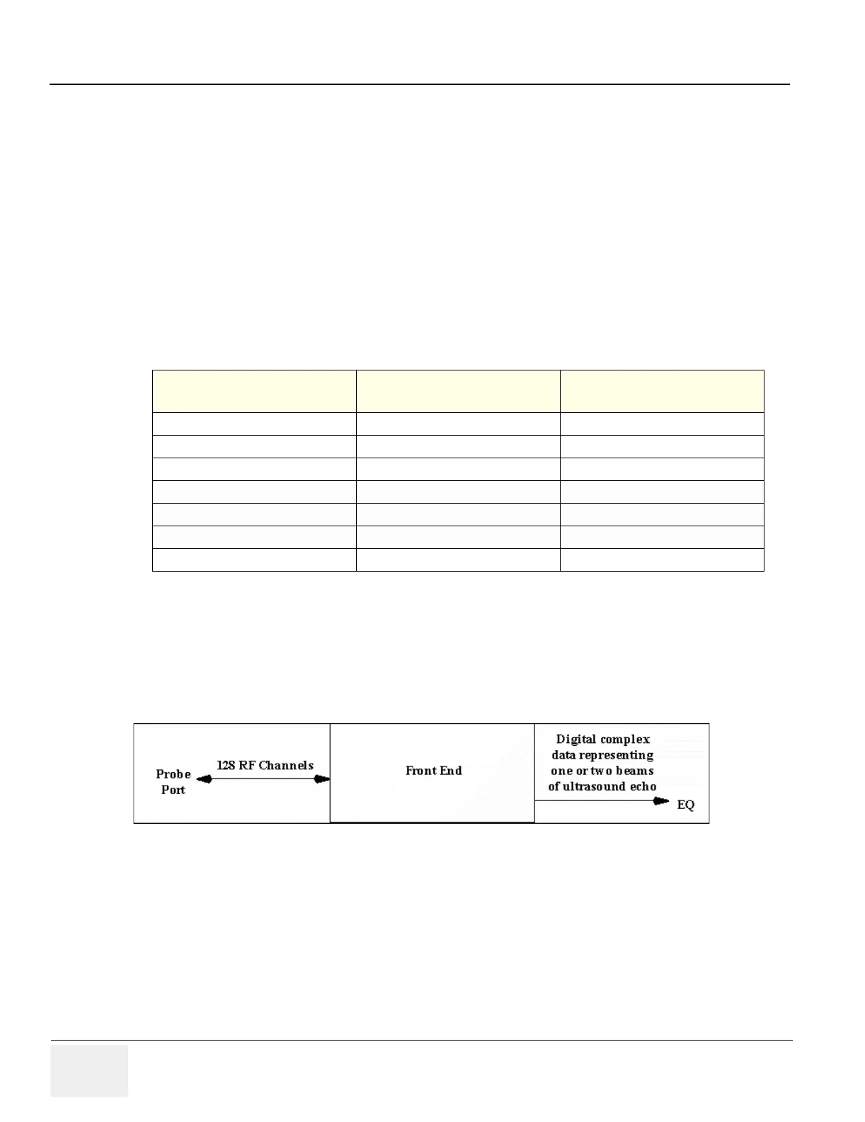
5-3-2 Front End Subsystem
The LOGIQ™ 9 Front End Subsystem consists the XDIF (Transducer Interface) board, RF Amp board
and eight TD (Transmit Delay) boards.
The Front End Subsystem provides 128 receive and 128 transmit channels as well as gain and
bandpass filtering of the received signal.
Table 5-2 FEPS, Output Comparison
System Name
FEPS, FEPS2, FEPS2.1
Nominal Output
FEPS3
Nominal Output
5VPA +5.05V +6.0V
5VNA -5.05V -6.0V
5VP +5.05V +5.05V
3V3 3.33V 3.33V
PHVP +121.2V / +24.2 +121.2V / +24.24V
12VP 12.12 13.0V
15VP +15.15 +15.15
Figure 5-4 Basic Front End SubSystem
 Loading...


