GE MEDICAL SYSTEMS PROPRIETARY TO GE
D
IRECTION 2294854-100, REVISION 3 LOGIQ™ 9 PROPRIETARY MANUAL
Chapter 8 Replacement Procedures 8-29
8-5-4 BEP 1 HDD Replacement (2366650) (cont’d)
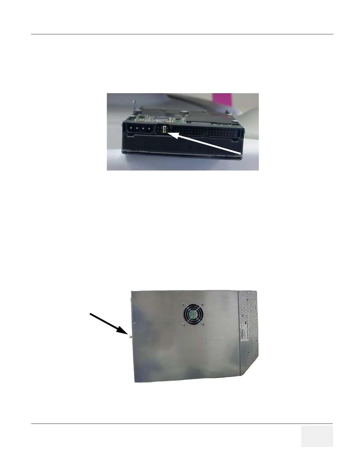
7.) Check the jumper on the back of the new HDD to ensure it is the same as the old one (Figure 8-25).
The only jumper on the back of the Hard Disk Drive (HDD) should be set to Cable Select (CS). Refer to
the diagram on the HDD to ensure that the CS jumper is in place. CS will allow Master/Slave
determination by the cable.
8.) Attach the new HDD to the tray with the four screws. See the orientation in Figure 8-24.
9.) Attach the power and IDE cables to the new HDD Assembly.
10.)Slide the assembly into the BEP chassis and ensure the chassis tabs engage the slots on the HDD
tray(Figure 8-23).
11.)Secure the HDD assembly with the single screw in the center (Figure 8-21).
8-5-5 BEP 2.X HDD Replacement (2348186-31)
1.) Remove the BEP cover by turning the retaining screw counter-clockwise (Figure 8-26). Pull the
back of the cover out and away from the BEP chassis.
2.) Unplug the Fan connected to the cover and set the cover aside.
3.) Locate the hard drive under the MOD or CD-RW drive tray and disconnect the power and IDE
cables from the drive (Figure 8-27).
Figure 8-25 HDD EIDE Jumper
Figure 8-26 BEP 2.X Cover with Fan
 Loading...


