GE MEDICAL SYSTEMS PROPRIETARY TO GE
D
IRECTION 2294854-100, REVISION 3 LOGIQ™ 9 PROPRIETARY MANUAL
7-24 Section 7-7 - Acquisition Diagnostics
7-7-4-2 Board-Level BMP Diagnostics
• All Board-Level BMP Diags: Tests vector generation and Scan Bus emulation on the BMP. This
configuration further tests the SCB's Clock Generation and PCI bridge, but does not rely on the
Scan Sequencer or Image Port functions of the SCB.
Not tested on the BMP, with this diagnostic, are its abilities to receive and correctly process the
TxSync, RxSync, IQ data, and Scan Bus inputs, as well as its ability to drive the BM output data to
the SCB. These functions will be tested with a system-level diagnostic.
The following subsections outline the Board-Level BMP Diagnostics.
• BMP PCI Interface Diag: Tests the Host’s ability to communicate with the BMP via the PCI bus.
NOTE: A preferred test strategy for the PCI 9054 Interface is detailed in Section 7-8.
• BMP Memory Diag: Tests all of the on-board memory, including registers.
NOTE: Guidelines in Section 7-9 will enumerate the memory locations.
• BMP Signal Path Diag: Tests the entire BMP signal path with a series of input vectors and scan
parameters (both from the on-board test vector generator), whose results are each read out of a
FIFO in the BM Output section of the board.
The following BMP functions are tested:
- Synthetic Aperture - Dynamic Range Compression
- Axial Interpolator - Edge Enhance
-Detector -Splicer
- Vector Compounder - BM Output, with exception of the output signal drivers
- Rate Converter - Memory Banking
The BM data read from the Output block's FIFO may then be compared to gold file data for
verification and fault isolation.
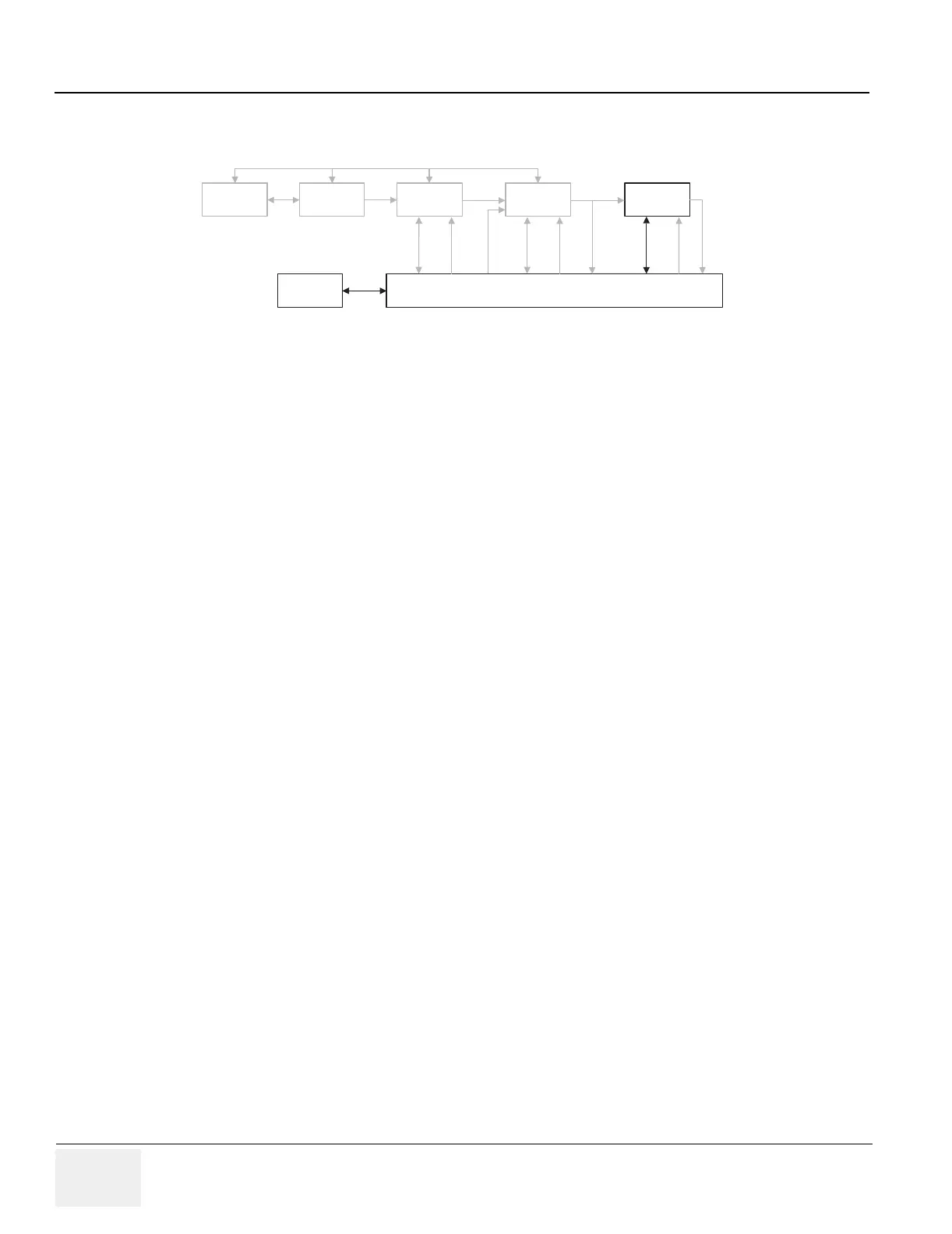
Figure 7-22 Board-Level BMP Block Diagram
XDIF/RF TD’s EQ BMP
Scan Control Board
Host
PCI
PCI
PCI
IQ,
RxSYNC
BM
IQ
IIC
RF
Probe
RF
TD
CTRL
TxSYNC
RxSYNC
TxSYNC
TxSYNC
 Loading...


