GE MEDICAL SYSTEMS PROPRIETARY TO GE
D
IRECTION 2294854-100, REVISION 3 LOGIQ™ 9 PROPRIETARY MANUAL
8-128 Section 8-33 - Internal I/O Replacement Procedure
Section 8-33
Internal I/O Replacement Procedure
8-33-1 Manpower
1 person, 1 hour 30 minutes
8-33-2 Tool
Long Phillips screwdriver, size 2.
8-33-3 Preparations (click here to view the cover removal video)
1.) Power Down/Shutdown the system as described in Section 4-3-2 on page 4-3.
2.) Remove the Side Covers as described in Section 8-2-2 on page 8-5.
3.) Remove Rear Covers as described on Section 8-2-6 on page 8-10 and Section 8-2-3 on page 8-7.
4.) Remove the External I/O as described in Section Section 8-32 on page 8-126.
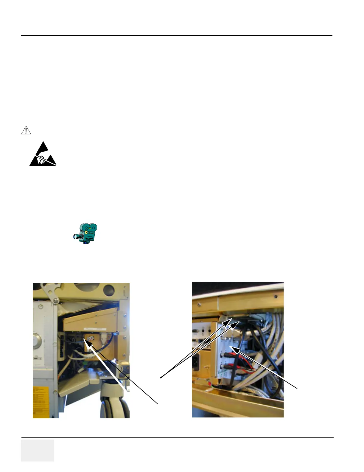
5.) Disconnect the cables connected to the I/O on both sides.
WARNINGWARNING
Do not touch any boards with integrated circuits prior to taking the necessary ESD
precautions:
1.) Always connect yourself, via an arm-wrist strap, to the advised ESD connection
point located on the Rear of the scanner (to the right of the power connector).
2.) Follow general guidelines for handling of electrostatic sensitive equipment.
Select the movie camera icon to view the video of the cover
removal and installation procedures.
Figure 8-139 Internal I/O Removal
Screw
Internal I/O
Screws
Backend Processor side
External I/O side
 Loading...


