GE MEDICAL SYSTEMS PROPRIETARY TO GE
D
IRECTION 2294854-100, REVISION 3 LOGIQ™ 9 PROPRIETARY MANUAL
8-124 Section 8-31 - Fan Assembly Replacement Procedure
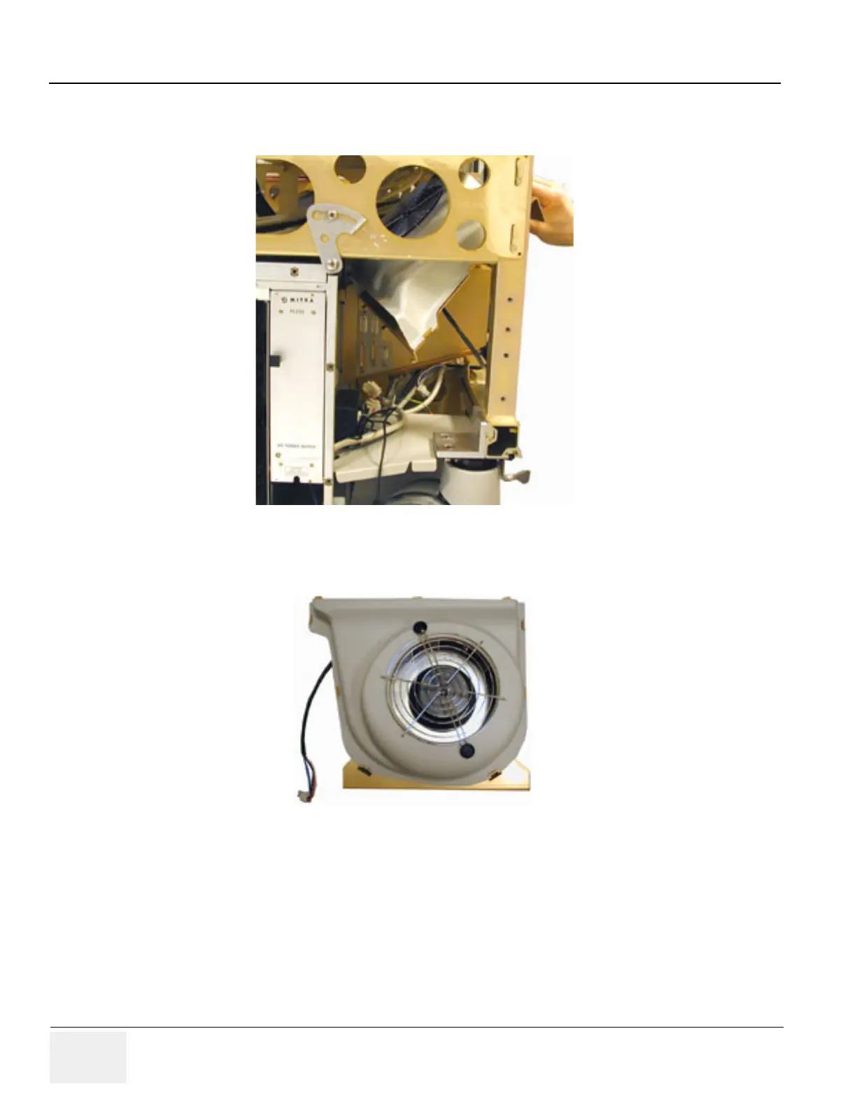
8-31-4 Fan Assembly Removal Procedure (cont’d)
8-31-5 Fan Assembly Installation Procedure
1.) Remove the shroud from the replacement Fan Assembly
2.) Thread Fan assembly in the same way as it was taken out. Be careful with the External I/O
connector, located on the side of the Internal I/O.
3.) Replace the Fan Assembly Shroud.
4.) Hitch up Fan Assembly on Board Rack sidewall.
5.) Fasten the assembly to the chassis with one (1) screw.
Figure 8-133 Fan Assembly Removal
Figure 8-134 Fan Assembly
 Loading...


