GE MEDICAL SYSTEMS PROPRIETARY TO GE
D
IRECTION 2294854-100, REVISION 3 LOGIQ™ 9 PROPRIETARY MANUAL
Chapter 8 Replacement Procedures 8-107
8-25-5 AC Controller Installation Procedure
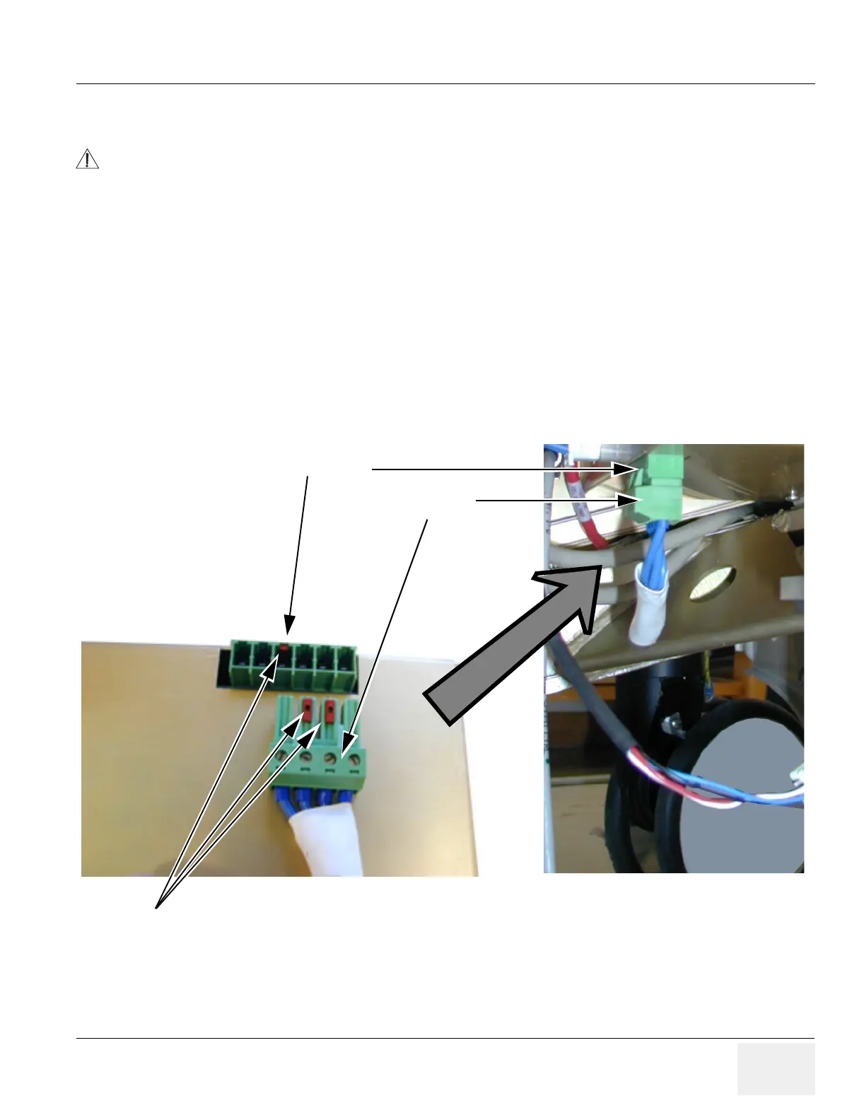
1.) Connect the cables. You may need to leave the Speed Control cable and the Fan cable
unconnected until you have fastened the unit. Input Voltage connector and socket are coded
to prevent mistakes. In 115V system the connector matches one end of the 8-holed socket. In
230V system it matches the other end of the socket. Figure 8-117 is on a 230V system, and
the connector can only be plugged in the right end of the socket.
2.) Fasten AC Power Module for correct Voltage and connect the remaining cables.
3.) Mount the Rear Covers as described in Section 8-2-3 on page 8-7 and in Section 8-2-6 on
page 8-10.
4.) Mount Side Covers as described in Section 8-2-2 on page 8-5.
5.) Do functional check-out.
DANGER
Before installing a replacement unit, verify that the power selector on the AC
Power Module is set to the correct voltage for the peripherals used on the
system.
Figure 8-117 Input Voltage connector/socket
4 pin connector
8 holed socket
Red blocks prevents wrong connections
 Loading...


