GE MEDICAL SYSTEMS PROPRIETARY TO GE
D
IRECTION 2294854-100, REVISION 3 LOGIQ™ 9 PROPRIETARY MANUAL
8-126 Section 8-32 - External I/O Replacement Procedure
Section 8-32
External I/O Replacement Procedure
8-32-1 Manpower
1 person, 1 hour
8-32-2 Tool
Long Phillips screwdriver, size 2.
8-32-3 Preparations (click here to view the cover removal video)
1.) Power Down/Shutdown the system as described in Section 4-3-2 on page 4-3.
2.) Remove the Right Side Cover as described in Section 8-2-2 on page 8-5.
3.) For full control during installation procedure: Remove the Upper Rear Cover as described in
Section 8-2-3 on page 8-7 and the Lower Rear Cover in Section 8-2-6 on page 8-10.
8-32-4 External I/O Removal procedure
1.) Disconnect all cables to and from the External I/O Assembly.
2.) Unscrew two Phillips screws fastening it to the chassis leg.
3.) Unscrew the Phillips screw on the Internal I/O rear wall and pull the Assembly free from the socket
it is plugged into.
WARNINGWARNING
Do not touch any boards with integrated circuits prior to taking the necessary ESD
precautions:
1.) Always connect yourself, via an arm-wrist strap, to the advised ESD connection
point located on the Rear of the scanner (to the right of the power connector).
2.) Follow general guidelines for handling of electrostatic sensitive equipment.
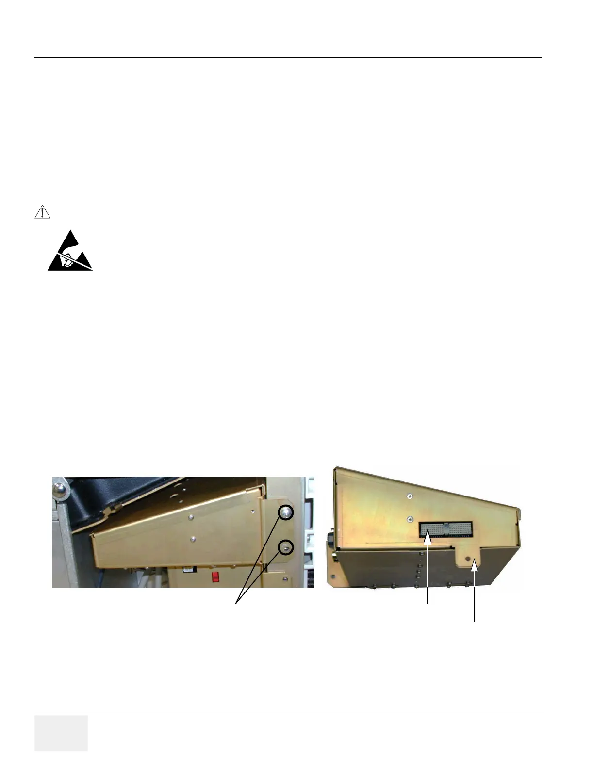
Figure 8-136 Side Views of the External I/O Assembly
Screws (2) External I/O Plug
Flange for fastening the external I/O to the
internal I/O just below the socket/plug
connection.
 Loading...


