GE MEDICAL SYSTEMS PROPRIETARY TO GE
D
IRECTION 2294854-100, REVISION 3 LOGIQ™ 9 PROPRIETARY MANUAL
Chapter 6 Service Adjustments 6-13
6-6-4 Brake Arm Adjustment Procedure
To adjust the brake arm it is recommended to separate both front adjustment nuts from the brake
assembly.
2.) Remove the brake clamps that are inserted through a small hole in the front adjustment nuts and
slipped over the nut at its collar.
3.) Loosen the front retaining nuts to allow room for adjustments.
4.) With a screwdriver you can pry the front adjustment nuts away from their connectors in the brake
assembly.
5.) Set the main brake - the brake assembly should be pulled to the left.
6.) Seat the right adjustment rod into the right adjustment nut under the right front wheel as far as it will
go.
7.) Seat the right front adjustment nut onto the adjustment rod as far as it will go.
8.) In order to insure that the same length of adjustment rod is seated into the two adjustment nuts you
will turn the adjustment rod one turn out of the rear adjustment nut under the front wheel and turn
the front adjustment nut off the adjustment rod a similar turn.
9.) Repeat this alternating rotation until the front adjustment nut lines up easily with the connector in
the brake assembly.
10.)Push the adjustment nut onto the brake assembly connector and secure the retaining nut tight
against the adjustment nut.
NOTE: Repeat the same procedure to adjust the swivel lock. The only difference would be to set the swivel lock
prior to the adjusments.
6-6-5 Procedure Completion
1.) Install the front bumper.
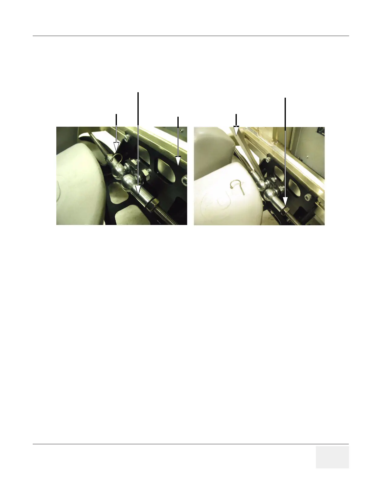
Figure 6-10 Front Adjustment Hardware
Brake Clamp
Screwdriver
Adjustment Nuts
Retaining Nuts
Brake Assembly
 Loading...


