GE MEDICAL SYSTEMS PROPRIETARY TO GE
D
IRECTION 2294854-100, REVISION 3 LOGIQ™ 9 PROPRIETARY MANUAL
8-122 Section 8-31 - Fan Assembly Replacement Procedure
Section 8-31
Fan Assembly Replacement Procedure
8-31-1 Manpower
One person, 1 hour
8-31-2 Tools
Phillips screwdriver, size 2.
8-31-3 Preparations (click here to view the cover removal video)
1.) Power Down/Shutdown the system as described in Section 4-3-2 on page 4-3
2.) Remove the Right and Left Covers as described on Section 8-2-2 on page 8-5.
3.) Remove Upper Rear Cover and Filter as shown in Section 8-2-3 on page 8-7.
4.) Remove the Lower Rear Cover as shown in Section 8-2-6 on page 8-10.
NOTE: There are washers and magnetic lock for Upper Rear Cover on the upper screws.
5.) Remove the Top Cover as shown in Section 8-2-4 on page 8-8.
6.) Remove the Rear Handle ashown in Section 8-2-8 on page 8-12.
7.) Remove the filter media.
.
8-31-4 Fan Assembly Removal Procedure
1.) Unscrew four (4) Phillips screws that fasten Cover Air Duct. See Figure 8-132.
2.) Push down the lower side of Cover Air Duct to free lower ends of the Filter Frame. Remove Filter
Frame downwards.
3.) Becarful of sharp edges. Move Cover Air Duct up in the front, then backwards, off the Fan Assembly
and out of the System.
Select the movie camera icon to view the video of the monitor
replacement procedure.
6 minutes and 23 seconds
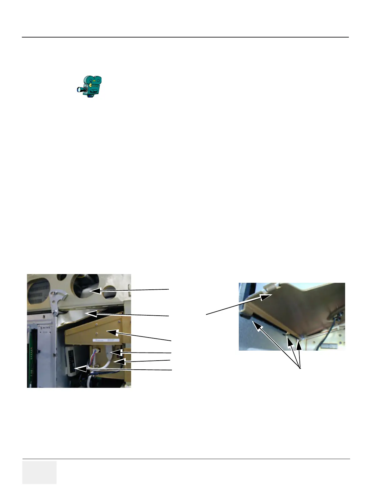
Figure 8-131 Fan Assembly, location and hitch up
Fan assembly
External I/O
Fan Cover Air Duct
AC Controller Module
Modem
Fan Cable
Hitch up
 Loading...


