GE MEDICAL SYSTEMS PROPRIETARY TO GE
D
IRECTION 2294854-100, REVISION 3 LOGIQ™ 9 PROPRIETARY MANUAL
Chapter 5 Components and Functions (Theory) 5-7
5-3-2-1 XDIF (Transducer Interface) Board
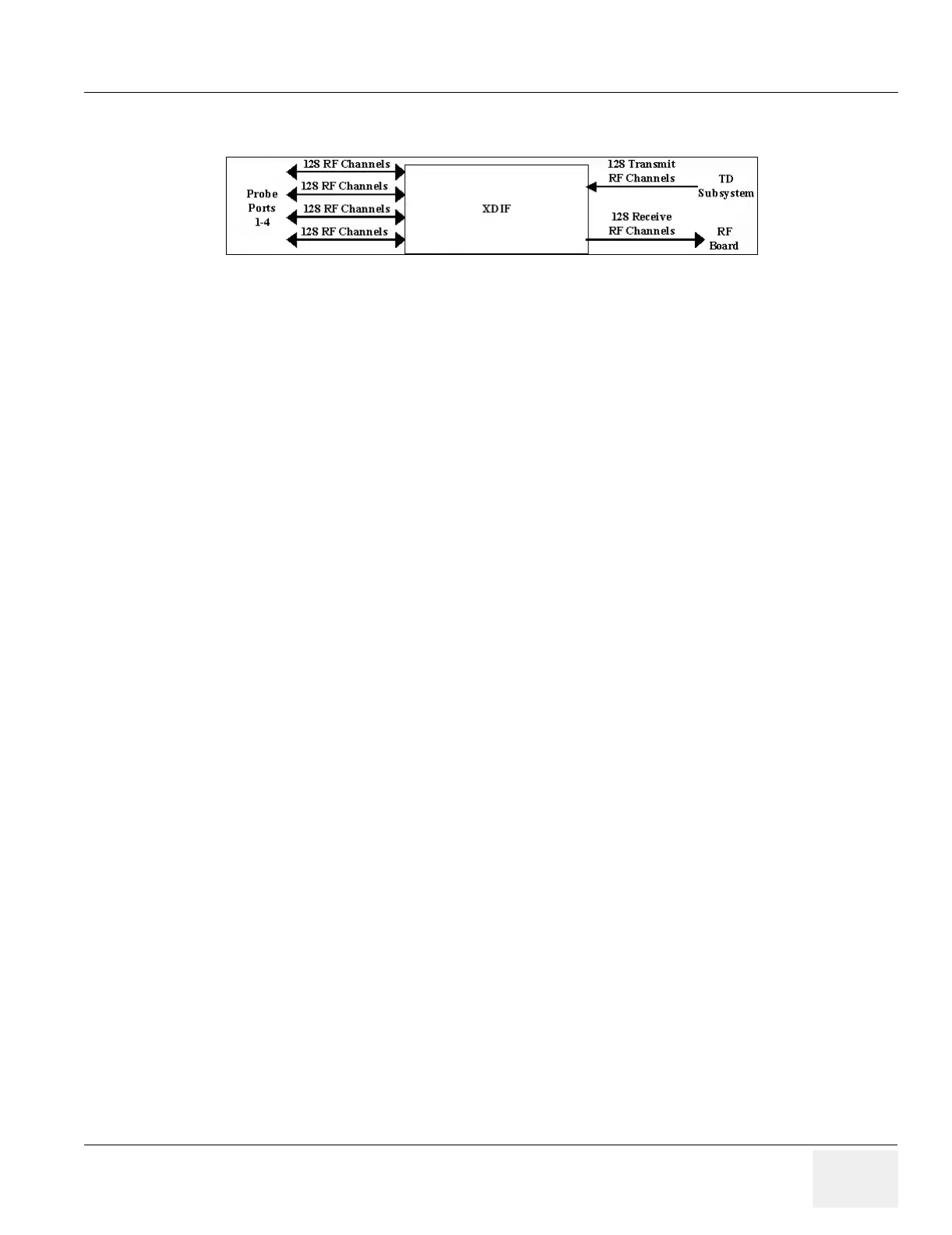
The XDIF supports four 128 Channel probe ports with the ability to select one of the four probe ports.
The XDIF supports a probe multiplexer requiring a 200V (+100V and -100V). The multiplexer in the
probe will select 128 of the out of up to 192 channels.
The XDIF uses a T/R (Transmit/Receive) switch on each output to the RF Amplifier board. During
transmit the T/R switch prevents the high voltage transmit pulser from damaging the receive
preamplifier. During receive the T/R switch isolates the receive preamp from the transmit high voltage
pulser.
5-3-2-2 Top Plane
Connects the receive signals from the XDIF board to the RF Amplifier board at the front of the circuit
boards.
Figure 5-5 XDIF Board Functions
 Loading...


