GE MEDICAL SYSTEMS PROPRIETARY TO GE
D
IRECTION 2294854-100, REVISION 3 LOGIQ™ 9 PROPRIETARY MANUAL
5-40 Section 5-7 - Internal I/O
5-7-1 Location in the Unit
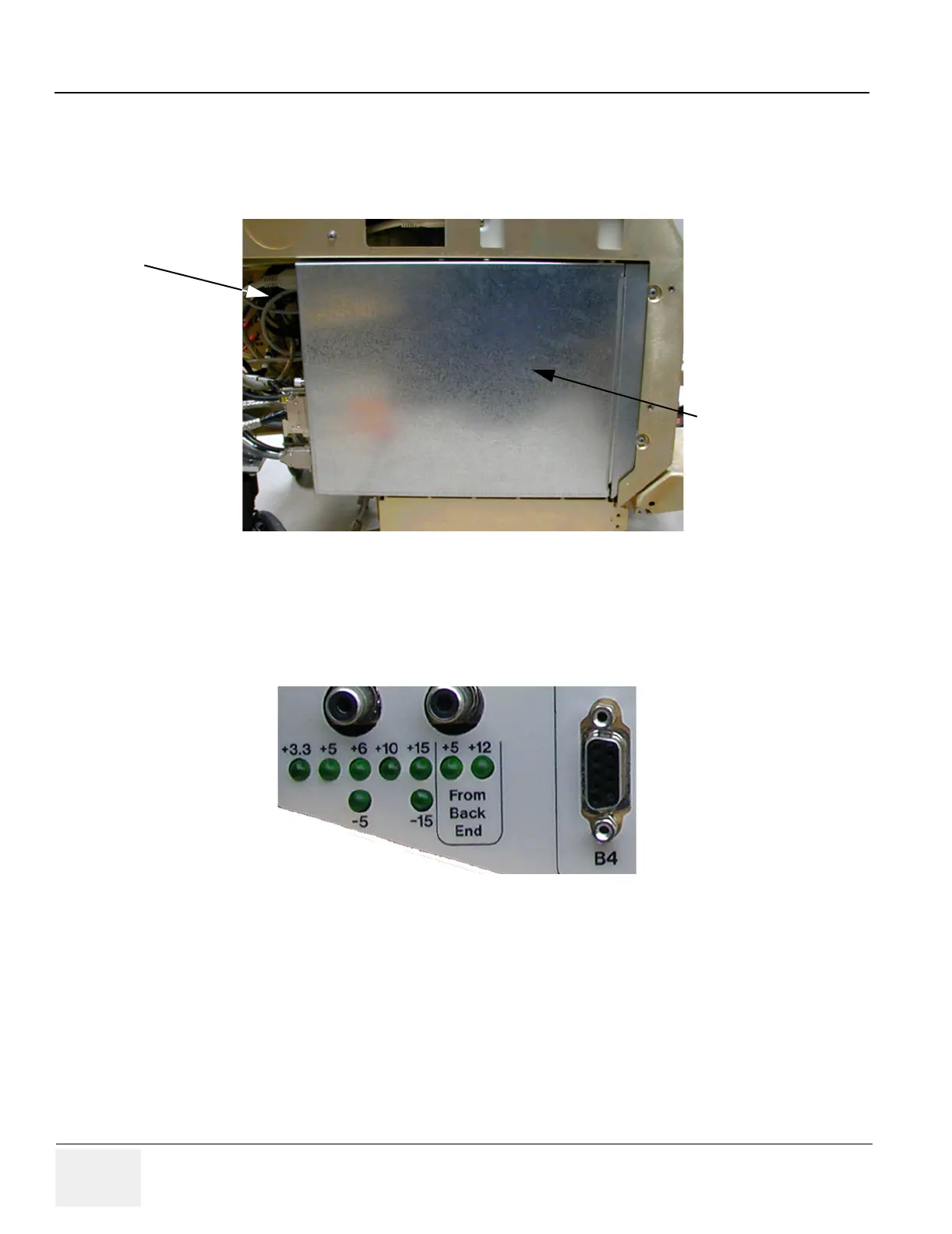
The Internal I/O Module is plugged into the Card Rack (at the end nearest to the rear of the system).
5-7-2 LEDs
Nine green LEDs indicate that the respective DC Voltages are OK.
5-7-3 Fuses
All output voltages are fused
5-7-4 Jumpers and Dip-switches
TBD
Figure 5-29 Internal I/O: Location in the System (Seen from Left Side)
Figure 5-30 Internal I/O: Green LEDs for Power Status.
Backend Processor
Back of System
Internal I/O
(behind all the cables)
 Loading...


