P44x/EN ST/Hb
P442, P444 (ST) 4-
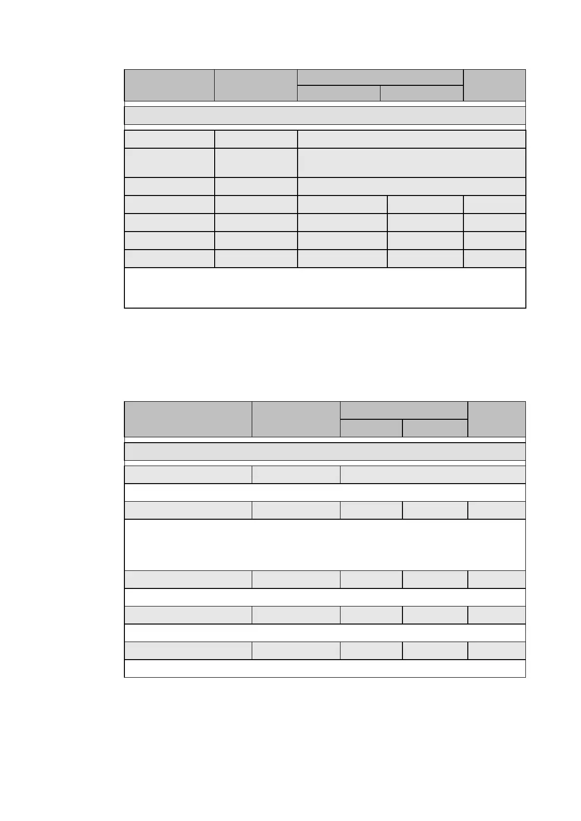
Menu text Default setting
Setting range
Step size
GROUP 1 – NEG SEQUENCE O/C
I2>4 Status Disabled Disabled, Enabled
I2>4 Directional Non Directional Non-directional, Directional FWD, Directional
REV
I2>4 VTS Block Block Block, Non-directional
I2>4 Current Set 0.20 x In 0.08 x In 4.00 x In 0.01 x In
I2>4 Time Delay 10.00 s 0 s 100.0 s 0.01 s
I2>4 Time VTS 0.200 s 0 s 100.0 s 0.01 s
I2> Char angle - 45° -95° 95° 1°
Where negative phase sequence current may flow in either direction through a relay
location, such as parallel lines or ring main systems, directional control of the element
should be employed (see section P44x/EN AP).
2.6 Maximum of Residual Power Protection – Zero Sequence Power Protection (“Zero Seq
Power” menu)
The ‘Zero Seq Power’ menu is displayed when ‘CONFIGURATION/Earth Fault Prot’ cell is
set to “Zero Seq Power”.
The following chart shows the adjustment menu for the zero-sequence residual overcurrent
protection, the adjustment ranges and the default in-factory adjustments.
Menu text Default setting
Setting range
Step size
Min Max
GROUP1 – ZERO-SEQ. POWER
Zero Seq. Power Status Activated Activated / Disabled
Setting that enables or disables the zero sequence power protection.
K Time Delay Factor 0 0 2 0.2
Setting for the K time delay factor. The K time delay factor adjusts the IDMT T(s) time-delay.
T(s) = K × (S
ref
/S
r
) where:
– S
ref
= Reference residual power
– S
r
= Residual power generated by the fault
Basis Time Delay 1s 0 s 10 s 0.01s
Setting for the basis time delay.
Residual Current 100mA 50mA 1A 10mA
Setting for the residual current.
Residual power 500 mVA 300 mVA 6.0 VA 30.0 mVA
Setting to adjust the residual power threshold.
 Loading...


