b6
CM) 9-26
MiCOM P40 Agile P442, P444
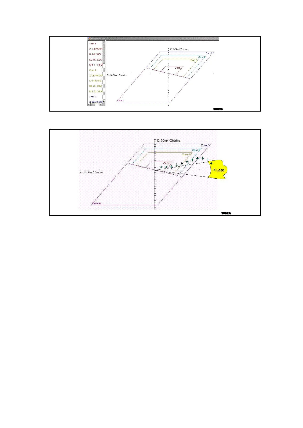
Figure 8: Example of Z-graph screen (Rio format can be created as well)
Figure 9: Evolving impedance from the load area to the final fault impedance in
Zone1
To simulate a fault in a zone, it is necessary to vary the current progressively to move the
point from the load area into the desired zone.
A single-phase starting characteristic with different values of K0 can be created:
(K0x = (Zx0 - Z1) /(3 Z1).
(In S1 there are up to four possibilities KZ1 & KZ2, KZp, KZ3/4)
This solution is carried out in case of an underground cable/overhead line section (KZ1 ≠
KZ2 = KZp = KZ3/4) where the Z01 & Z02 angles can be very different (HV Line at 80° and
cable at 45°).
Nevertheless, the most common injection devices do not allow several values of K0 to be
handled (the same for Z-Graph); therefore, for accurate control of zone limits, it will be
necessary to generate several characteristic files (as many Rio files as KZ values.
 Loading...


