b6
Firmware D
-14 MiCOM P40 Agile
The IRIG-B board can also be specified with a fibre optic transmitter/receiver which can be
used for the rear communication port instead of the RS485 electrical connection (IEC60870
only) and with the second rear communication board (see next section).
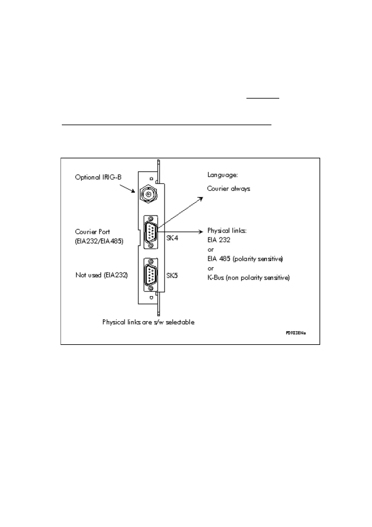
2.7 2nd rear communications board
For relays with Courier, Modbus, IEC 60870-5-103 or DNP3 protocol on the first rear
communications port, the Courier protocol is used with an optional second rear
communications port. The communication protocol network uses twisted pair K-Bus (non
polarity sensitive), twisted pair EIA(RS)485 (connection polarity sensitive) or EIA(RS)232.
The second rear comms board and the IRIG-B board are mutually exclusive since they use
the same hardware slot: Two versions of the second rear comms board are available; one
with an IRIG-B input and one without. The physical layout of the second rear comms board is
shown in Figure 4.
Figure 4: Rear comms. port
2.8 Ethernet and redundant boards
The Optional Ethernet board supports network connections of the following type:
• 10BASE-T
• 10BASE-FL
• 100BASE-TX
• 100BASE-FX
The optional Redundant Ethernet board (ZN0071) has 6 variants (refer to Px4x/EN REB user
guide):
• redundant Ethernet (SHR protocol) with modulated or un-modulated IRIG-B,
• redundant Ethernet (RSTP protocol) with modulated or un-modulated IRIG-B,
• redundant Ethernet (DHS protocol) with modulated or un-modulated IRIG-B.
The optional 9-2 Ethernet board is the communication interface between MiCOM protection
and the network. In the MiCOM Px4x protection, the 9-2 Ethernet board replaces the
conventional analogue inputs (analogue module) wherever it/they stand.
 Loading...


