P44x/EN AP/Hb
MiCOM P40 Agile P442, P444
(AP) 5-
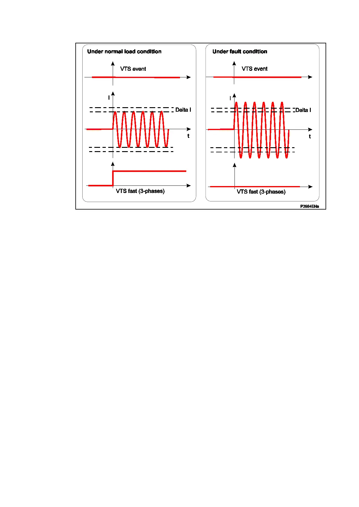
Figure 100: Line energisation – superimposed current under fault condition (VT
isolated)
The phase voltage level detector is settable (’Threshold 3P’ setting)).
The sensitivity of the superimposed current – ‘delta I>’– elements is settable and default
value is set to 0.1In.
Caution: If line is energised at nominal current, delta I> has to be set at In + 20% for
instance.
5.8.1.2.3 Absence of Three Phase Voltages on Line Energisation
If a VT were inadvertently left isolated prior to line energisation, incorrect operation of voltage
dependent elements could result. The previous VTS element detected three phase VT failure
by absence of all 3-phase voltages with no corresponding change in current. On line
energisation there will, however, be a change in current (as a result of load or line charging
current for example). An alternative method of detecting 3-phase VT failure is therefore
required on line energisation: in that case the SOTF logic is applied.
5.8.1.3 Internal logic of the VT Failure detection
The VT failure (fuse blowing or fuse failure detection) alarm is given when the following
conditions are met:
• VT Failure is internally detected and the VTS time-delay is elapsed (VT failure &
VTS_Time_delay)
• Or the opto input dedicated to the function receives a fuse blowing signal (VTS opto
input energised).
The equation (Figure 101) of the VT failure is:
Fuse Failure (confirmation of the fuse blowing) =
(“Fuse Failure detected” AND “VTS Time-Delay”)
OR “opto input energized”
The VT protection fuse blowing is detected when the following conditions are met:
• VN>: The residual voltage is higher than a fixed threshold:= 0,75Vn
• NOT I0>: The zero-sequence current is higher than I0> threshold:
• NOT I2>: The negative sequence current is higher than a I2> threshold (identical to
the I0 threshold).
 Loading...


