Measurements and Recording
P44x/EN MR/Hb
MiCOM P40 Agile P442, P444
(MR) 7-
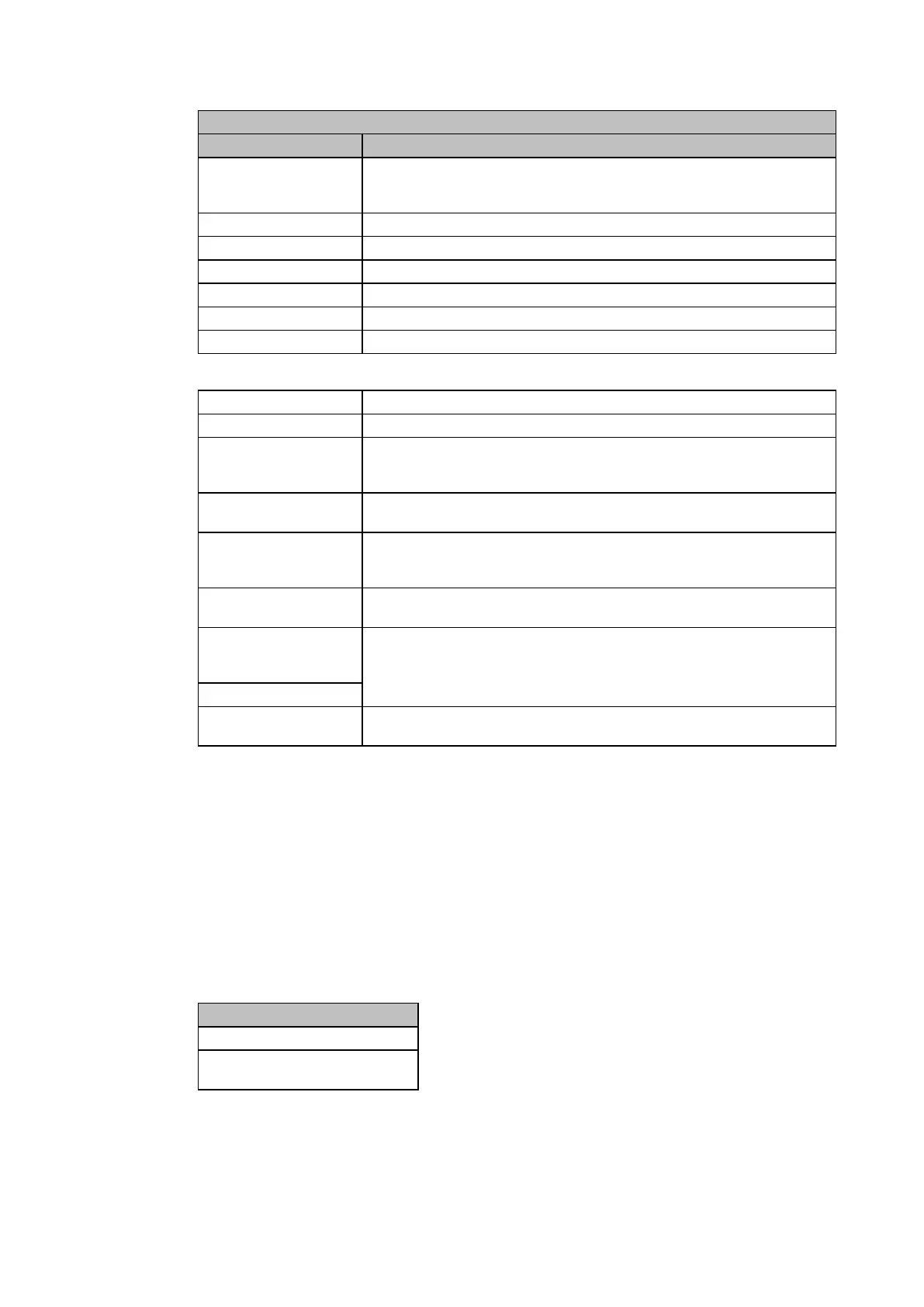
VIEW RECORDS
LCD Reference Description
Fault Location
When calculated the fault location can be found (distance in km or miles,
impedance or percentage of line length, set in ‘MEASUREMENT SETUP’
column). See section 1.4.
IA Magnitude of phase A current
IB Magnitude of phase B current
IC Magnitude of phase C current
VAN Magnitude of phase A voltage
VBN Magnitude of phase B voltage
VCN Magnitude of phase C voltage
Fault Resistance Fault resistance
Fault in Zone None, Zone 1, Zone 2, Zone P, Zone Q, Zone 3 or Zone 4
Trip Elements 2
Trip I2>2, Trip I2>3, Trip I2>4, Trip VN>1, Trip VN>2, Trip Zq, Trip V<3,
Trip V<4, Trip V>3, Trip V>4, Trip I<1, Trip I<2, Trip F<1, Trip F<2, Trip
F<3, Trip F<4, Trip F>1, Trip F>2
Start Elements 2
Start V<3, Start V<4, Start V>3, Start V>4, Start I<1, Start I<2, Start F<1,
Start F<2, Start F<3 ,Start F<4, Start F>1 or Start F>2
Select Report
Setting range from 0 to 4.
This selects the required maintenance report from the possible 5 that may
be stored. A value of 0 corresponds to the latest report and so on.
Report Text
Up to 32 Character description of the occurrence (refer to following
sections)
Report Type
These cells are numbers representative of the occurrence. They form a
specific error code which should be quoted in any related correspondence
to AREVA T&D P&C Ltd.
Report Data
Reset Indication
Either Yes or No. This serves to reset the trip LED indications provided that
the relevant protection element has reset.
For extraction from a remote source via communications, refer to Chapter P44x/EN CM,
(Commissioning) where the procedure is fully explained.
Types of Event
An event may be a change of state of a control input or output relay, an alarm condition,
setting change etc. The following sections show the various items that constitute an event.
1.2.2 Change of state of opto-isolated inputs.
If one or more of the opto (logic) inputs has changed state since the last time that the
protection algorithm ran, the new status is logged as an event. When this event is selected to
be viewed on the LCD, three applicable cells will become visible as shown below;
Opto input Events
“LOGIC INPUTS”
“Event Value
0101010101010101”
The Event Value is an 8 or 16 bit word showing the status of the opto inputs, where the least
significant bit (extreme right) corresponds to opto input 1 etc. The same information is
present if the event is extracted and viewed via PC.
 Loading...


