44x/EN AP/Hb6
-98 MiCOM P40 Agile
• Earth fault elements
• Broken conductor elements
• Negative phase sequence influenced thermal elements
4.4.2 Directionalising the Negative Phase Sequence Overcurrent Element
Directionality is achieved by comparison of the angle between the negative phase sequence
voltage and the negative phase sequence current and the element may be selected to
operate in either the forward or reverse direction. A suitable relay characteristic angle setting
(I2> Char Angle) is chosen to provide optimum performance. This setting should be set
equal to the phase angle of the negative sequence current with respect to the inverted
negative sequence voltage (- V
2
), to be at the centre of the directional characteristic.
The angle that occurs between V2 and I2 under fault conditions is directly dependent upon
the negative sequence source impedance of the system. However, typical settings for the
element are as follows:
• For a transmission system the RCA should be set equal to -60°
• For a distribution system the RCA should be set equal to -45°
4.5 Maximum of Residual Power Protection – Zero Sequence Power Protection (“Zero Seq
Power” menu)
The aim of this protection is to provide the system with selective and autonomous protection
against resistive phase to ground faults. High resistive faults such as vegetation fires cannot
be detected by distance protection.
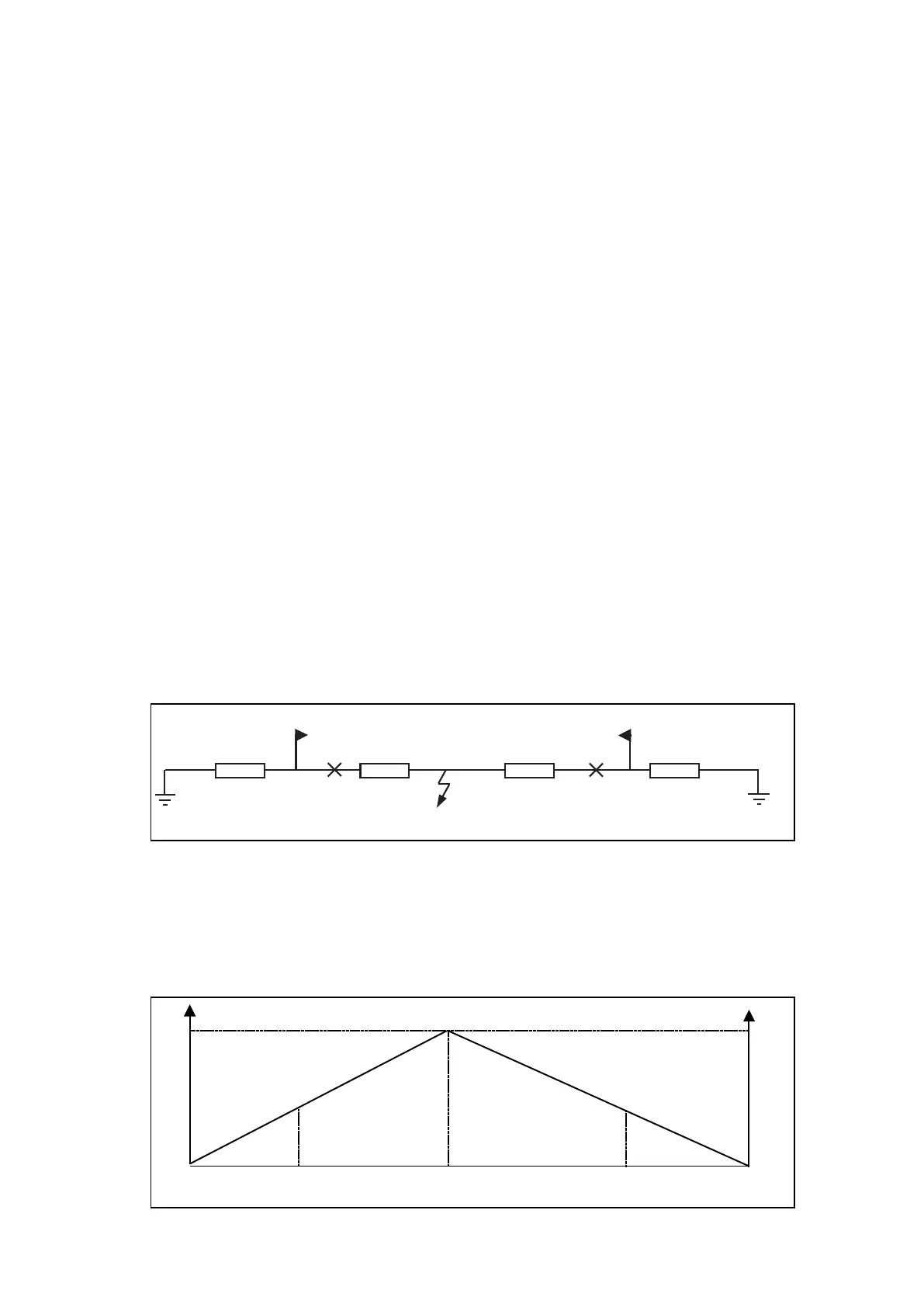
When a phase to ground fault occurs, the fault can be considered as a zero-sequence power
generator. Zero-sequence voltage is at maximum value at the fault point. Zero-sequence
power is, therefore, also at maximum value at the same point. Supposing that zero-
sequence current is constant, zero-sequence power will decrease along the lines until null
value at the source’s neutral points (see below).
Z
os1
x .Z
ol
(1-x).Z
ol
Z
os2
P
A
P
B
P3100XXa
Figure 67: Zero sequence
Where:
Zos1: = Zero-sequence source side 1 impedance
Zol = Zero-sequence line impedance
Zos2 = Zero-sequence source side 2 impedance
x = Distance to the fault from P
A
.
P
o
V
o
1
0,5
0
1
0,5
0
P
A
P
B
Fault
P3101ENa
Figure 68: Zero sequence decreasing along the line
 Loading...


